Do you have a question about the ABB A140-M65 and is the answer not in the manual?
Explains the manual's purpose, target audience, and availability.
Provides contact details for ABB Turbocharging Service Stations.
Discusses design variants and accuracy of illustrations in the document.
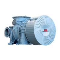
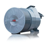
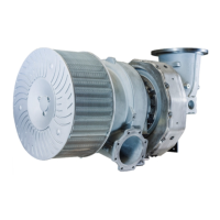
Details the components and operational principles of the turbocharger.
Explains symbols, notes, warnings, and abbreviations used in the manual.
Provides guidelines for storing new turbochargers and spare parts.
Introduces safety aspects and responsibilities related to turbocharger operation.
Explains personal protective equipment (PPE) and mandatory safety signs.
Defines warning and caution symbols and their implications for safety.
Specifies the intended applications and limitations of the turbocharger.
Addresses turbocharger behavior and checks after a deflagration event.
Details the locations and importance of warning plates on the turbocharger.
Explains the information provided on the turbocharger rating plate.
Outlines requirements for periodic checks of pressure vessels used with the turbocharger.
Provides safety instructions for lifting turbocharger components and assemblies.
Specifies requirements for personnel and modifications before operation and maintenance.
Identifies noise hazards and hazards from hot surfaces during operation and maintenance.
Details safety measures for hot surfaces, rotating parts, and operational procedures.
Covers occupational safety, risk of falling, and safe maintenance practices.
Provides weight specifications and lifting gear requirements for turbocharger transport.
Describes the procedure for disconnecting pipes and loosening the turbine cleaning connection.
Details procedures for fastening turbochargers with oil-cooled or water-cooled bearing casings.
Explains the correct procedure for loosening clamping nuts to prevent damage.
Provides instructions for safely positioning the turbocharger for storage.
Describes the process of inserting gaskets into the turbocharger bracket.
Details requirements and procedures for fitting threaded rods for turbocharger installation.
Explains how to correctly position and align the turbocharger on its mounting bracket.
Provides instructions and torque values for fastening the turbocharger using standard nuts.
Details preparations and procedures for tightening the turbocharger clamping nut.
Covers introduction, pre-lubrication, oil filtering, and oil pressure requirements.
Outlines visual checks, monitoring, and measurements before and during commissioning.
Describes steps for recommissioning a turbocharger after a period of inactivity.
Details admissible lubricating oil pressure and temperature limits at the turbocharger inlet.
Explains the importance of monitoring exhaust gas temperature and its relation to operating limits.
Discusses the speed measuring system and its layout.
Addresses noise hazards and insulation measures for turbochargers.
Covers general service work, interval recommendations, and specific checks.
Lists recommended replacement intervals for rotating and non-rotating turbocharger components.
Provides crucial instructions for safely stopping the engine and turbocharger.
Introduces periodic maintenance and recommends cleaning procedures during operation.
Details the procedure, options, limits, causes, and consequences of compressor cleaning.
Explains the process for cleaning the turbine stage during operation, including causes of contamination.
Provides guidelines for preparing and selecting tools for mechanical cleaning of components.
Details how to clean non-rotating parts of the compressor end.
Covers cleaning procedures for non-rotating parts at the turbine end.
Provides general precautions for cleaning the cartridge group to prevent corrosion.
Explains how to clean the compressor end of the cartridge group, including agent selection.
Details the soaking and cleaning procedure for the turbine end of the cartridge group.
Lists possible causes and remedies for delayed start-up, vibrations, and rubbing.
Covers low oil pressure, reduced/increased speed, and high exhaust gas temperature.
Addresses high charge air pressure and reduced compressor performance.
Explains causes and remedies for continuous, periodic, and sporadic turbocharger surging.
Details malfunctions related to the speed measurement system, including signal issues and incorrect speed readings.
Introduces safety precautions for dismantling and fitting procedures.
Lists required materials, tools, and lifting equipment for dismantling and fitting.
Provides a breakdown of the weights for various turbocharger assemblies.
Details the steps for removing the air inlet components from the turbocharger.
Outlines the procedure for removing the insulation and the gas outlet casing.
Explains how to remove the gas outlet flange using press-off screws.
Details the process of removing the compressor casing and its internal components.
Describes the use of a press-off tool for casing removal, emphasizing caution.
Provides instructions for removing the cartridge group, including oil orifice precautions.
Details the steps for removing the nozzle ring and its associated components.
Explains how to install the cartridge group onto a service support using specific tools.
Outlines the procedure for measuring critical clearances within the turbocharger.
Details the correct procedure for installing the nozzle ring and its sealing components.
Explains how to lift, rotate, and install the cartridge group into the turbine casing.
Emphasizes the critical role of turbine casing insulation and burst protection.
Details the installation process for the wall insert, diffuser, and compressor casing.
Describes the procedure for measuring radial clearances N and R.
Explains how to install the filter silencer or air suction branch using a V-clamp.
Details the procedure for installing the gas outlet flange and measuring radial clearance.
Provides instructions for fitting the insulation to the turbine casing.
Details the steps for installing the gas outlet casing and its insulation.
Lists tightening torques for various screw connections on the turbocharger.
Outlines emergency repair options and safety precautions for oil leaks.
Describes procedures for installing a replacement turbocharger or cartridge group.
Details the steps for fitting a cover plate to the turbine casing.
Explains mothballing procedures based on the state of engine lubricating oil.
Discusses variants for turbocharger preparation when the engine is out of operation for over 12 months.
Guides users on how to order spare parts, including required information.
Provides illustrations and part numbers for oil-cooled cartridge spare parts.
Provides illustrations and part numbers for water-cooled cartridge spare parts.
Shows illustrations and part numbers for turbine casing (1 inlet) spare parts.
Shows illustrations and part numbers for turbine casing (2 inlets) spare parts.
Illustrates and lists spare parts for axial gas outlet casings.
Illustrates and lists spare parts for radial gas outlet casings.
Illustrates and lists spare parts for the compressor casing.
Illustrates and lists spare parts for the filter silencer.
Illustrates and lists spare parts for the axial air suction branch.
Illustrates and lists spare parts for the radial air suction branch.
Illustrates and lists spare parts for the oil-cooled bearing casing.
Illustrates and lists spare parts for the water-cooled bearing casing.
Illustrates and lists spare parts for rotor and bearing parts.
Lists the required customer tool set and ordering information.
| Brand | ABB |
|---|---|
| Model | A140-M65 |
| Category | Industrial Equipment |
| Language | English |