ACH550-UH User’s Manual 1-181
Parameters
8121 REG BYPASS CTRL 0, 1 1 0 (NO)
Selects Regulator by-pass control. When enabled, Regulator by-pass control provides a simple control mechanism
without a PID regulator.
• Use Regulator by-pass control only in special
applications.
0 =
NO – Disables Regulator by-pass control. The drive
uses the normal PFA reference: 1106
REF2 SELECT.
1 =
YES – Enables Regulator by-pass control.
• The process PID regulator is bypassed.
Actual value of PID is used as the PFA reference
(input). Normally
EXT REF2 is used as the PFA
reference.
• The drive uses the feedback signal defined by
4014
FBK SEL (or 4114) for the PFA frequency
reference.
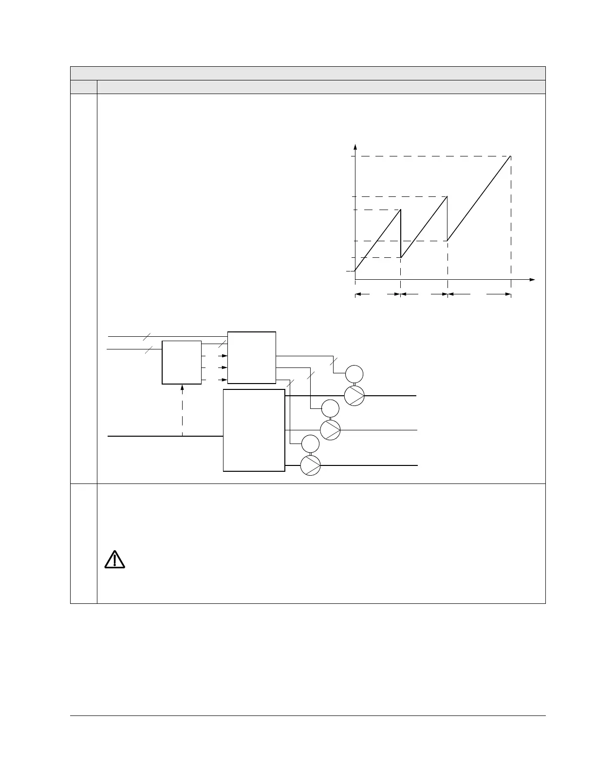
• The figure shows the relation between the control
signal 4014
FBK SEL (OR 4114) and the speed
regulated motor’s frequency in a three-motor
system.
Example: In the diagram below, the pumping station’s
outlet flow is controlled by the measured inlet flow (A).
8122 PFA START DELAY 0.00…10.00 s 0.01 s 0.50 s
Sets the start delay for speed regulated motors in the system. Using the delay, the drive works as follows:
• Switches on the contactor of the speed regulated motor – connecting the motor to the ACH550 power output.
• Delays motor start for the time 8122 PFA START DELAY.
• Starts the speed regulated motor.
• Starts auxiliary motors. See parameter 8115 for delay.
WARNING! Motors equipped with star-delta starters require a PFA Start Delay.
• After the ACH550 relay output switches a motor on, the star-delta starter must switch to the star-connection and
then back to the delta-connection before the drive applies power.
• So, the PFA Start Delay must be longer than the time setting of the star-delta starter.
Group 81: PFA Control
Code Description Range Resolution Default S
P 4014
P 8110
P 8109
P 8113
P 8112
A = No auxiliary motors running
B = One auxiliary motor running
C = Two auxiliary motors running
A
B
C
(%)
f
OUT
f
MIN
f
MAX
M
3~
M
3~
M
3~
Outlet pipe3
Outlet pipe2
Outlet pipe1
P1
P2
P3
Sewage
tank
Contactors
P1
P2
P3
Mains 3~
3
3
3
3
ACH550
3
3
Inlet pipe
A