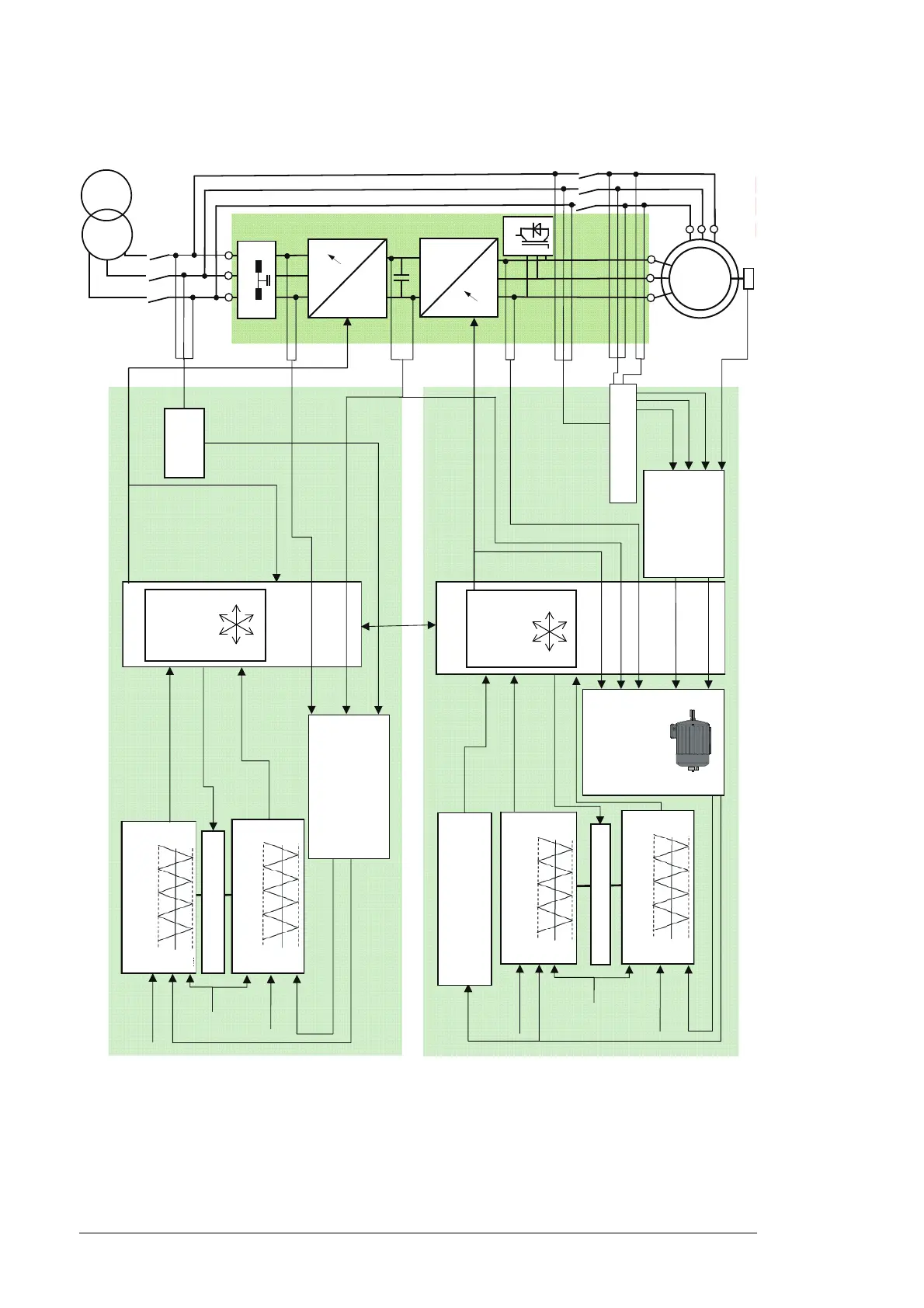
22 System description
The basic DTC block selects the inverter switch states so that tangential motion of the flux
vector is controlled by the torque error and the radial motion of the flux is controlled by the
flux error. The torque reference is supplied by the WTC. The torque feedback is calculated
by using stator-side quantities (at grid frequencies) ie, by a cross product of stator flux and
stator current.
RDCU
NDCU
Flux reference
Actual flux
P
ref
Torque
reference
Actual torque
Hysteresis band control
Two level hysteresis control
Three level hysteresis control
max
ref
min
max
ref
min
Torque and flux
calculation
Torque and flux
calculation
Flux bit
Switching frequency
Torque bits
ASIC
ASIC
Optimum
pulse
selector
Optimum
pulse
selector
Current
DC link voltage
Grid voltage
Switch position commands
Switch
positions
NAMU /
BAMU
(optional)
NUIM
Actual flux
Flux reference
Actual flux
P
ref
Torque
reference
Actual torque
max
ref
min
max
ref
min
Flux sector identification
Hysteresis band control
Two level hysteresis control
Three level hysteresis control
Flux bit
Switching frequency
Torque bits
Adaptive generator
model
Switch position commands
Switch positions
DC link voltage
Rotor current
Actual flux
Actual torque
Grid flux
Stator flux
Stator current
Rotor position
LCL
filter
ISU
INU
crowbar
DFIG

 Loading...


