26 System description
Reactive power is transferred only if there is an amplitude difference between the two
voltage vectors. Reactive power transfer equation is following:
For the desirable magnitude and direction of the power and reactive power flow, the length
of the converter voltage vector and its phase angle (with respect to the grid voltage vector)
must be controlled. The DC voltage is controlled by keeping the power (energy) balance
between the grid and grid-side converter in the DC link constant. The sign of the angle
determines the direction of the power flow. The output AC voltage is controlled by setting
the length of the flux reference to correspond to the desired output voltage level producing
cosfii = 1.0.
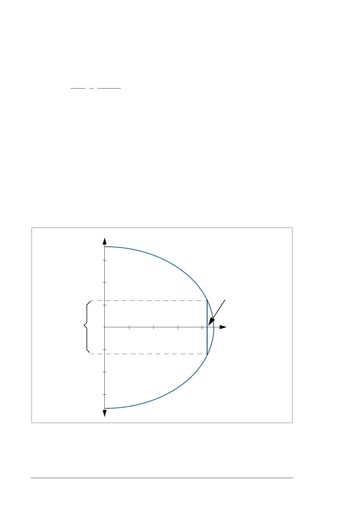
The grid-side converter can control reactive power independently of speed and active
power. The maximum reactive current capacity is approximately 80% of the active current
capacity and depends on the rating of the grid-side converter and on the electrical power
network voltage. An example curve of reactive power capability as a function of the active
power is shown below.
0.25 0.5 0.75 1.00
0
0.25
0.5
0.75
0
-0.25
-0.5
-0.75
Converter nominal power
P (p.u.)
Q (p.u.)
Reactive
power
capability at
nominal power

 Loading...


