80 Practical examples
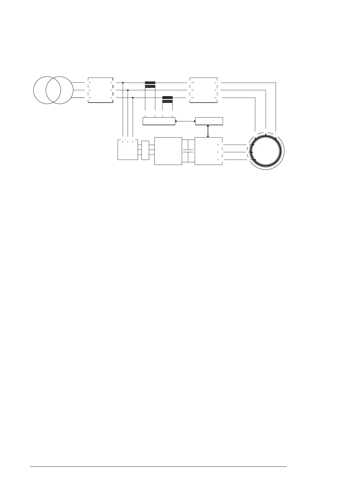
shown below. In this example the parameter 16.20 GRID CONNECT MODE is set to
MCB1+MCB3/B.
The maximum measurable stator current must be set by a parameter. The value is
calculated with the following equation:
CT = current transformer ratio
The polarity of a current transformer is determined by the direction the coils are wound
around the core (clockwise or counterclockwise) and the way the leads are brought out of
the transformer case. Current transformers have subtractive polarity and following
designations for installation: P1: primary current, line-facing direction; P2: primary current,
load-facing direction; and S1: secondary current. Correct polarity has to be taken into
account when installing and connecting current transformer to power metering.
Sometimes it is not possible to install current transformers mechanically so that current
flow is from P1 to P2 which is standard. This means that measurement polarity is
reversed. In this case the polarity can be corrected by entering a negative value in this
parameter.
MCB2
DFIG
INUISU
NUIM
X1:1
X1:2
X2:1
X2:2
L1
L2
L3
MCB3MCB1
NDCU
P1,K P2,L
S1,k S2,l
P1,K P2,L
S1,k S2,l
L1
L2
L3
L1
L2
L
3
W1
V1
U1
W1
V1
U1
K
L
M
U2
V2
W2
U2
V2
W2
L
C
L
99.28 MAX MEAS IS
4,5 V
2,73333 ohm
-----------------------------------
CT⋅=

 Loading...


