Electrical installation 71
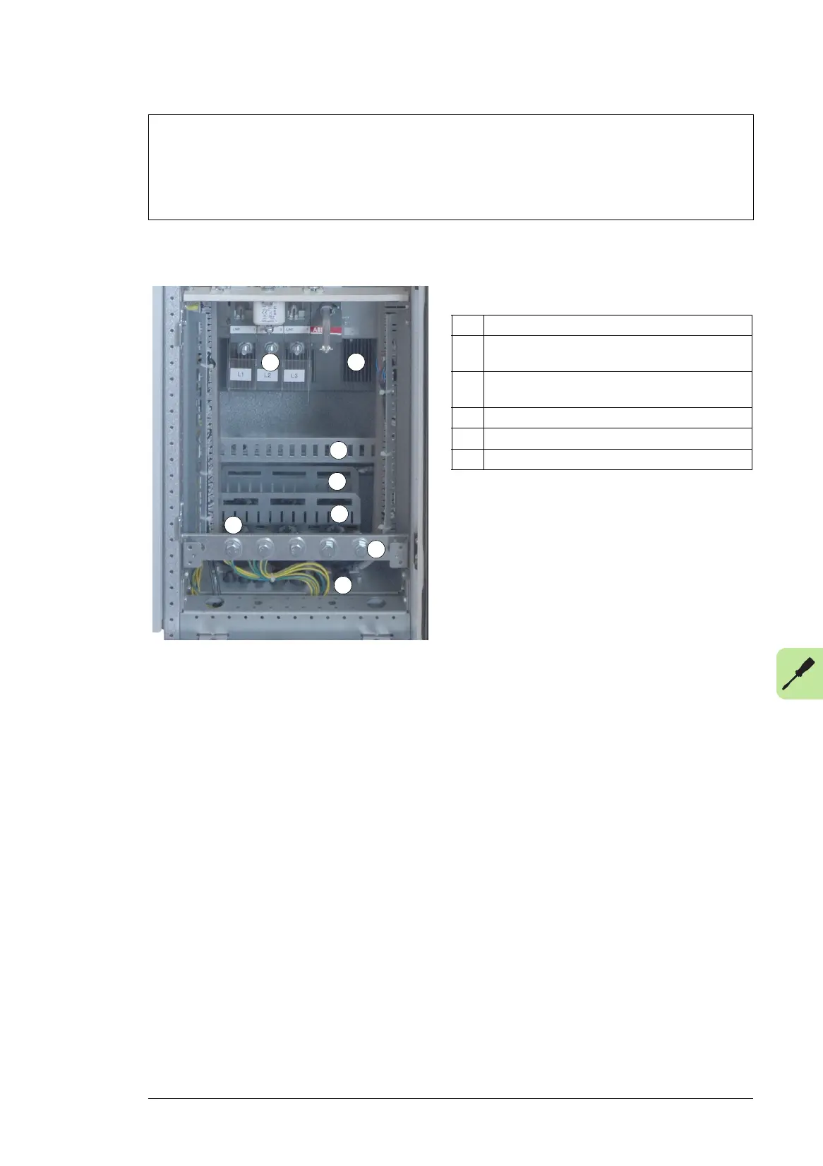
Layout of the power cable connection terminals and lead-throughs
(frames R6 to R9)
Note:
If there is a symmetrically constructed grounding conductor on the motor cable in addition to the conductive
shield, connect the grounding conductor to the grounding terminal at the drive and motor ends.
Do not use an asymmetrically constructed motor cable. Connecting its fourth conductor at the motor end
increases bearing currents and causes extra wear.
*) Switch-disconnector and separate fuses in frame R9
1 Strain relief
2 Power cable lead-throughs. Conductive sleeve
under the grommet.
3 Control cable lead-through with EMI conductive
cushions.
4 PE terminal
5 Input power cable terminals L1, L2 and L3
6 Motor cable terminals U2, V2, W2
5
2
3
1
6
4
1
1
 Loading...


