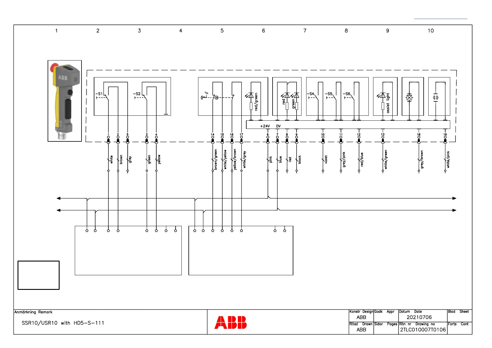
CONNECTION DIAGRAMS SENTRY
25 Back to table of contents
PCB for 24 VDC I/O
3-pos enabling switch Emergency stop Signal LED Front button Top buttons Home pos. Movement
+ -
HD5-S-111
SENTRY SSR 10 / USR 10
Test/Reset
SENTRY SSR 10 / USR 10
Test/Reset
A1
1L+
1M
1L+
1M
A2 T1 R1 T2 R2 X1 X4
PLe
According to
EN ISO 13849-1
Note: The stated PL is only valid if all relevant requirements according to EN ISO 13849-1/-2 are met. It is the responsibility of the
machine builder to make a risk assessment and make sure that the appropriate functional safety levels are achieved.
A1 A2 T1 R1 T2 R2 X1 X4
Safety Products