6
4 ELECTRICAL INSTALLATION
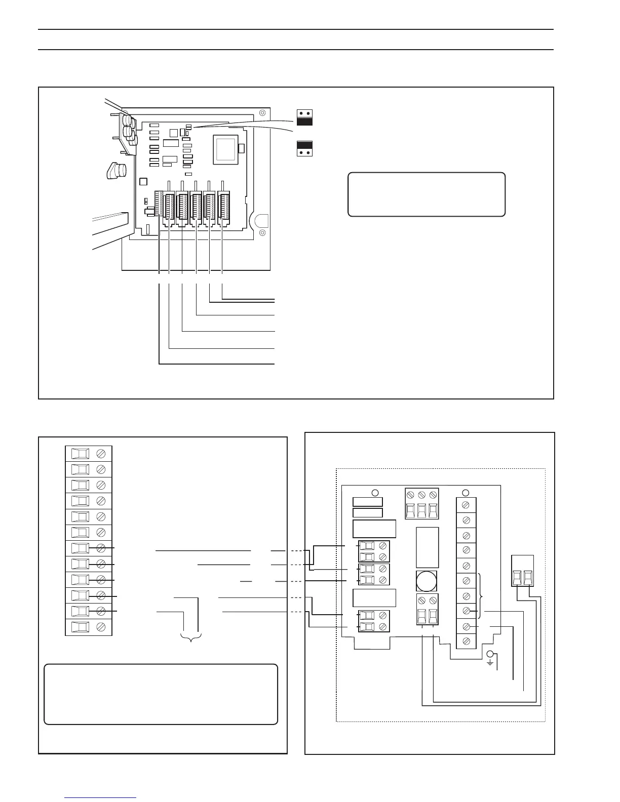
4.1 Identifying the Input/Output Modules (and accessing the Configuration Levels) – Fig. 4.1
Fig. 4.1 Identifying the Input/Output Modules
Information.
Digital input 1.1 is permanently allocated to the low
temperature divert event.
Relay 1.1 is permanently allocated to temperature
divert.
4.2 Standard Connections – Fig. 4.2 4.3 Dairy Relay Board Connections – Fig. 4.3
Refer to
IM/C1900-INS, Section 4.2
for input connections.
Additional Functions
Input 4 – (Blue Pen) Pressure/Flow (2nd RTD – indicate only)
Input 3 – Hot Water, Control O/P
Input 2 – (Green Pen) Cold Product, Control O/P (if required)
Input 1 – (Red Pen) Hot Product, Divert Relay, Event I/P
Module Positions
1
2 3 4 5 6
To allow access to the Configuration Levels,
move link 3 to the lower position
To prevent access to the Configuration Levels,
move link 3 to the upper position
LK3
LK3
Note. When the chart plate is
closed it can be sealed to prevent
access to LK3.
Fig. 4.3 FDA Dairy Relay Board Connections
1
2
7
8
9
10
11
12
Normally Open
Common
Logic 1* (Temp Divert)
3
4
5
6
Position 1
Common
Red
Black
Logic 2* (Sec'dy Divert [Optional])
Orange
Blue
Brown
Divert signal
*Event Input
Fig. 4.2 Standard Connections
Black
Red
Orange
Blue
Brown
N L
76
N/L2
L1
5
43
Position 6Position 5
RL2
RL1
TB2
TB5
N/O
C
TB1
L N
FS1
RL3
N/C C N/O
TB3
L1
C
TB4
IC1
IC2
L2
C
Ground
Line
Neutral
TB6
 Loading...