5
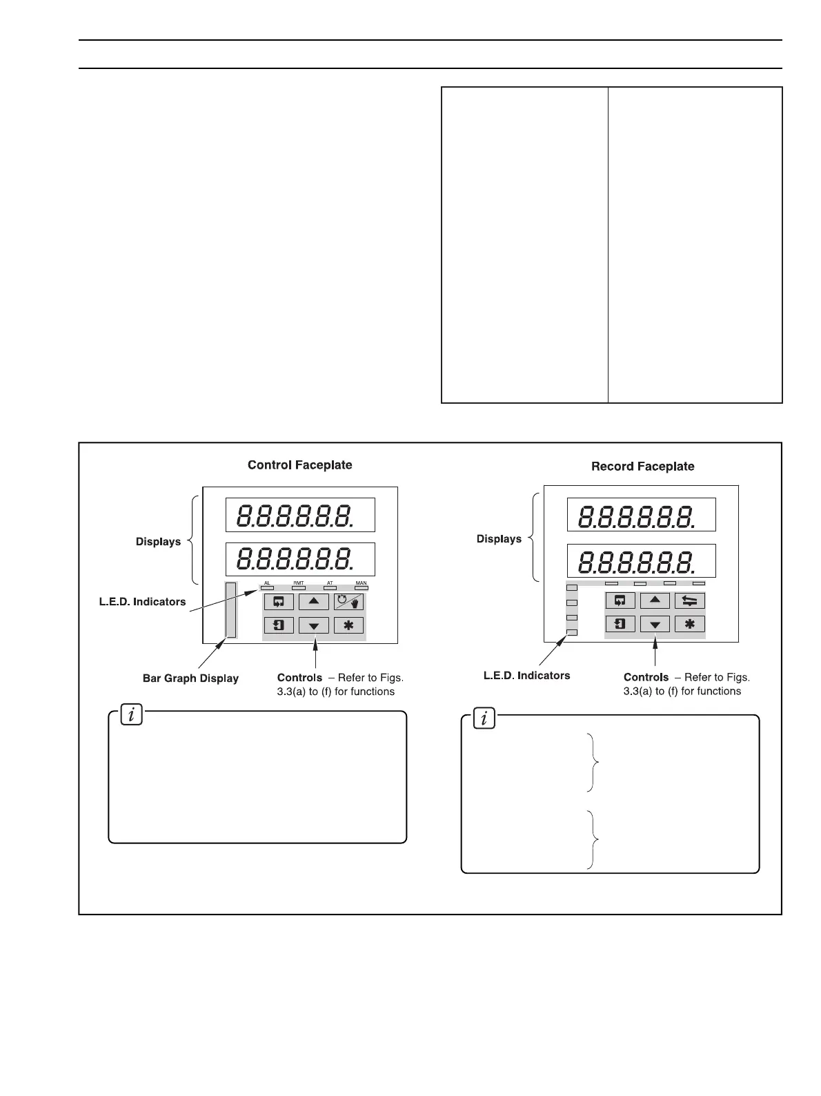
The displays, l.e.d. indicators and operation/programming
controls are located on the faceplates on the front panel of the
instrument – see Fig 3.1.
3.1 Displays and L.E.D. Indicators – Fig. 3.1
The displays comprise 2 rows of 6 characters.
At the top of each programming page (the page header) both
displays are used to describe the particular page selected.
When parameters within the selected page are viewed, the
upper display shows the parameter and the lower display
shows the value or setting for that parameter.
Alarm and Channel states are indicated by separate l.e.d.s on
the front panel faceplate(s) – see Fig. 3.1.
Status of process
variable alarms
Current channel displayed
Information.
AL1 – Channel 1
AL2 – Channel 2
AL3 – Channel 3
AL4 – Channel 4
CH1 – Channel 1
CH2 – Channel 2
CH3 – Channel 3
CH4 – Channel 4
Information.
An 11 segment
Bar Graph Display indicates
deviation of the measured value from the set point.
AL – States of alarms on controller channel
RMT – On if the Remote set point in use
AT – On if the instrument is in Automatic tuning
MAN – On if the instrument is in Manual control
mode
A
b
C
or
c
d
E
F
G
H
or
h
I
J
K
L
M
N
or
n
O
or
o
P
Q
r
S
t
U
V
Y
A
B
C
D
E
F
G
H
I
J
K
L
M
N
O
P
Q
R
S
T
U
V
Y
Fig. 3.1 Location of Displays, Controls and L.E.D. Indicators
Table 3.1 Character Set
3 DISPLAYS & CONTROLS