Type HCB-1 Pilot Wire Relay System 41-971.3M
17
Perform the tests as indicated in Figure 9 recording
the milliammeter readings and the relay input current
at the same instant, for future reference. The head-
ings “Circulating” and “Remote” in the table of Figure
9 refer to the test switch positions, “CIRC” and
“REM.” For tests 3 to 6 of Figure 9, the input current
should be increased to about 1.5 amperes by an aux-
iliary current transformer, if the secondary load cur-
rent is below this value. Also record the input and
output readings with the test switch in the “Local”
position. Typical values for the “Local” position read-
ings are shown in Figure 13.
9.3. THREE TERMINAL LINES
A similar procedure to Figure 9 should be followed
for three-terminal line applications. In this case open
the line circuit breaker at one terminal, and discon-
nect the leads from the pilot-wire terminals to the
insulating transformer (open H1 and H4) at the that
terminal. This leaves the remaining position of the
line operating as a two terminal line. Now perform the
normal tests as outlined for the two terminal line sys-
tem test. When these tests have been satisfactorily
completed, return the third terminal relay to normal
and close the breaker at that station. Repeat the
above procedure with a different breaker open and
relay disconnected. This will complete the check of
the three terminal line.
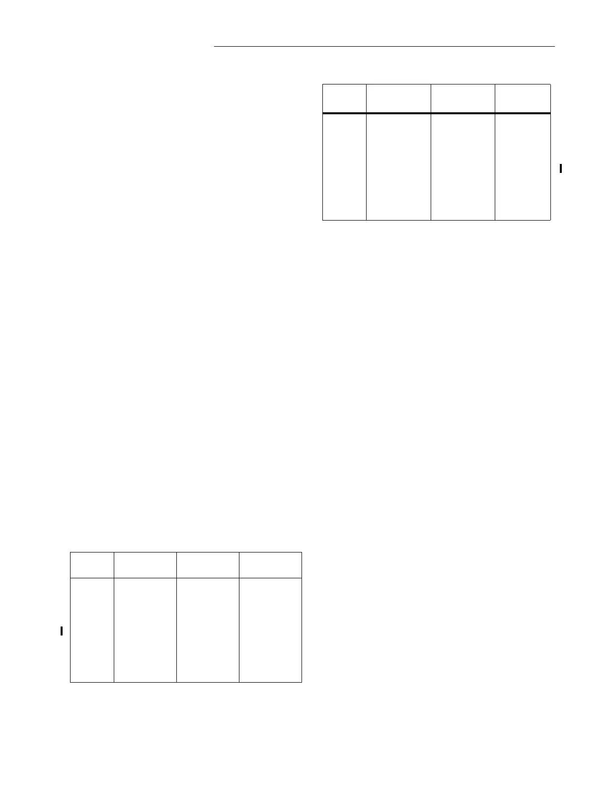
9.4. ENERGY REQUIREMENTS
The volt-ampere burden of the type HCB-1 relay is
practically independent of the pilot-wire resistance
and of the current tap used. The following burdens
were measured at a balanced three-phase current of
5 amperes:
The angles above are the degrees by which the current lags is
respective voltage.
The continuous rating of the relay is 10 amperes.
The two-second overload ratings of the relay are 150
amperes phase and 125 amperes ground currents.
9.5. PILOT-WIRE ENERGY
The current and voltage impressed on the pilot-wire
do not exceed 100 milliamperes and 60 volts. The
wave form and magnitude of the pilot-wire current
are such that telephone interference is within the lim-
its allowed by the local operating telephone com-
pany. This permits the use of leased telephone lines
as a pilot-wire channel.
10.0 RENEWAL PARTS
Repair work can be done most satisfactorily at the
factory. However, interchangeable parts can be fur-
nished to users who are equipped for doing repair
work. When ordering parts, always give the complete
nameplate data.
Relay
Taps
Phase A
VA Angle
Phase B
VA Angle
Phase C
VA Angle
A-F- 4
A-H- 10
B-F- 4
B-G- 4
B-H- 10
C-F- 4
C-H- 10
2.4 5°
3.25 0°
2.3 0°
3.98 0°
4.95 0°
2.32 0°
6.35 342°
0.6 0°
0.8 100°
0.63 0°
1.28 92°
2.35 90°
0.78 0°
3.83 80°
2.5 50°
1.28 55°
2.45 55°
.88 42°
0.3 60°
2.36 50°
1.98 185°
Relay
Taps
Phase A
VA Angle
Phase B
VA Angle
Phase C
VA Angle
A-F- 4
A-H- 10
B-F- 4
B-G- 4
B-H- 10
C-F- 4
C-H- 10
2.47 0°
7.36 0°
2.45 0°
16.82 9.90°
16.8 55°
2.49 0°
31.2 41°
2.110°
12.553°
2.0915°
16.7913.5°
22.050°
1.9915°
36.038°
1.97 20°
6.7 26°
2.07 10°
15.10 4.0°
12.3 38°
2.11 15°
23.6 35°