41-971.3M Type HCB-1 Pilot Wire Relay System
6
sequence current entirely, and operate the relay on
negative-plus-zero sequence current. Tap A is avail-
able to operate in this manner. The relay picks up at
about tap value for all phase-to-phase faults, but is
unaffected by balanced load current or three-phase
faults.
For ground faults, separate taps G and H are avail-
able for adjustment of the ground fault sensitivity to
about 1/4 or 1/8 of the upper tap plate setting. For
example, if the upper tap plate is set at tap 4, the
relay pick-up current for ground faults can be either 1
or 1/2 ampere. It is possible to eliminate response to
zero sequence current. Tap F provides such an oper-
ation.
The response of the relay to various types of faults
are summarized in the following tables.
The voltage, V
F
, impressed by the filter upon the sat-
urating transformer is:
Equ. (1)
Table 3 shows the values of the C-constants in Eq. (1).
For tap settings of C and H, the voltage, V
F
,
impressed by the filter upon the saturating trans-
former is:
Equ. (2)
4.1. SINGLE RELAY PICKUP (Pilot-wire Open) I
S
Single relay pickup, I
S
, is defined as the phase cur-
rent required to operate one relay with the pilot-wire
side of the insulating transformer open circuited (H1-
H4). The single relay pickup point in terms of filter
voltage is:
Equ. (3)
where T is the saturating transformer tap value. Sin-
gle relay pickup is defined by equating (2) and (3):
Equ. (4)
Current I
S
varies with the type of fault. For example,
for a 3 phase fault, I
S
= I
A1
, since only positive
sequence current is present. Substituting I
S
= I
A1
in
Equ. (4) and rearranging, the 3 phase fault pickup is:
Equ. (5)
For 4 Tap:
For a phase A to ground fault, if I
A1
= I
A2
= I
A0
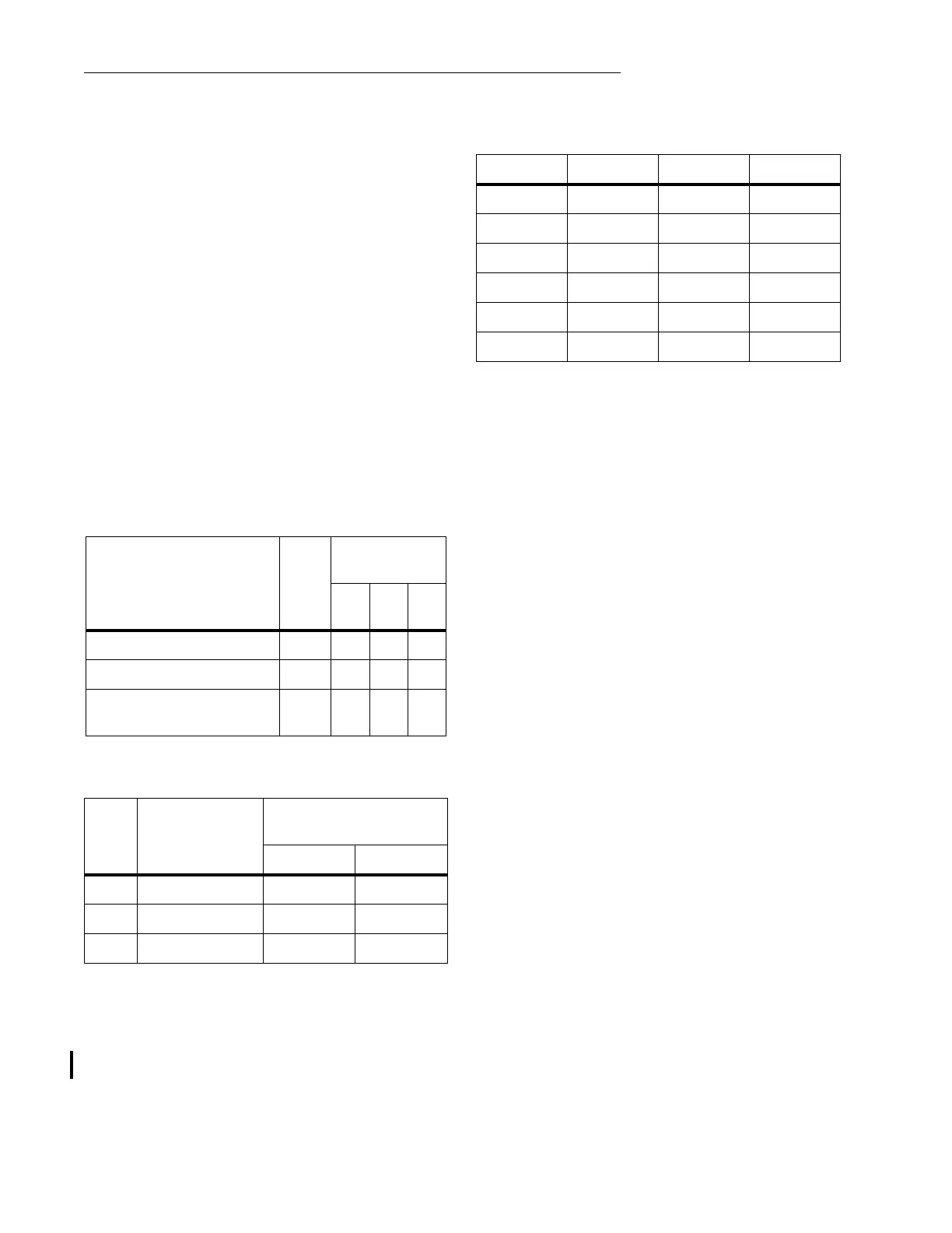
Table 1
Phase Faults
Sequence Components
in Sequence
Filter Output Taps
Pickup –
Multiples of T
3Ø
AB
CA BC
Pos., Neg., Zero C 1 .86 .53
Pos., Neg., Zero B 2 .9 .66
Neg., Zero A —
1.0
0
1.0
0
Table 2
Ground Faults
Com
b.
Lower Left
Tap
Ground Fault Pickup
Multiples of T Tap
Tap G Tap H
1C .25.12
2B .20.10
3A .20.10
V
F
C
1
I
A
1
C
2
I
A
2
C
0
I
0
++=
Table 3
Constants For Equation (1)
Tap C
1
C
2
C
0
A00.26—
B -0.08 0.34 —
C -0.20 0.46 —
F——0
G——2.5
H——4.9
V
F
.2
I
A
1
–.46
I
A
2
4.9
I
A
0
Volts++=
V
F
0.2
TTap
C()V
F
0.15
TTap
A()
==
V
F
0.16T (Tap B)=
0.2
T
0.2
I
A
1
–.46
I
A
2
4.9
I
A
0
++=
I
S
I
A
1
0.2
T
.2
-----------+
T
(3 phase fault)==
I
S
T
4 amp (3 phase fault)==