1.4.4 Replacement of auxiliary contacts
Positioning of auxiliary contacts, see fig. 5. The contacts are fixed with 4
screws. Remove the 2 links as shown in the fig. 11A Disconnecting cable (note
marking before removing switch and connect in same position).
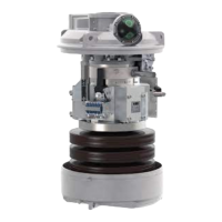
1.4.5 Replacement of motor
Motor is fixed with 4 screws. There are flat terminals for cables. See fig. 13.
1.4.6 Replacement of Damping device
When replacing the damping device, the closing spring must be charged. For
this work the release mechanism for the spring unit must be secured, see fig. 14.
Securing the device can be achieved with a G-clamp.
Note: For extra security both the opening and the closing springs must be
fastened. On one side of the damping device there is an adjustment screw. The
position of this screw should not be altered.
(21)
Fig - 13
(Replacement of Motor)
 Loading...