Do you have a question about the ABB H569-445 and is the answer not in the manual?
Provides contact details for customer service, training, technical support, and repair.
Information on accessing product manuals, brochures, and software online via a website.
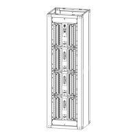
General description of the H569-445 Secondary DC Power Distribution Bay (BDFB/BDCBB).
Explains cabinet configuration for top/bottom cable entry and default panel labeling.
Defines load bus, termination, and cabinet capacity for loads.
Procedures for reconfiguring BDFBs in the field, such as feed conversion or load changes.
Details on breaker/fuseholder types and installation notes for distribution panels.
Discusses internal and external discharge return bus bar options, with advantages and drawbacks.
Describes the VIM1C meter's features, monitoring capabilities, and alarm functions.
Information on connecting output alarms, ABS power, and return connections for meters/alarms.
Covers safety statements, installation tools, and hardware requirements before installation.
Instructions for unpacking the BDFB, verifying contents, and checking site conditions.
Details on floor mounting procedures, anchor kits, and isolation/leveling kits.
Information on optional cabinet extensions for G7 and G8 models to match adjacent cabinet heights.
Instructions for installing an optional top cover for bottom-feed applications on cabinets.
Location of frame ground connections and specifications for lug landings.
Step-by-step procedure to convert a top-feed cabinet to a bottom-feed configuration.
Procedure to reconfigure BDFB load counts from 2-load to 4, 6, or 8-load configurations.
Detailed wiring diagram for panel connections specific to G7 and G8 models.
Detailed wiring diagram for panel connections specific to G101 and G102 models.
Wiring diagram illustrating alarm connections for G7 and G8 models.
Wiring diagram illustrating alarm connections for G101 and G102 models.
General safety statements regarding installation, environmental limits, and regulations.
Detailed safety precautions for installation, servicing, and handling hazardous energy.
| Brand | ABB |
|---|---|
| Model | H569-445 |
| Category | Circuit breakers |
| Language | English |