Page 15
© Copyright 2021 ABB. All rights reserved.
Discharge return bus options for terminating fuse or circuit breaker return leads may either be
internally mounted in the cabinet or externally mounted outside the distribution bay on a cable
rack.
Internal
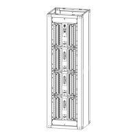
The internal discharge return bus bar option terminates return cables from the battery plant at the
top (and/or bottom) of the cabinet as shown in Figure 6 and Figure 7. There is a left-side bus that
interconnects to return bars mounted on the left mounted fuse or circuit breaker panels and a right
-side bus for the right mounted panels. The bus at the top of the cabinet is designed for
terminating six or eight 3/8 inch double-hole terminal lugs on 1 inch centers with a tongue width up
to 1.7 inches wide. Each panel mounted discharge return bus is designed for terminating up to 2
gage cable with 1/4 inch double-hole terminal lugs on 5/8 inch centers.
Advantage: The advantage of internal returns is that load leads are paired at the fuse or circuit
breaker and eliminates the need for identification tags on each return lead.
Drawbacks: Both the top and bottom input return connections are required to reach BDFB full
output capacity.
Return capacity limit per side:
only Top OR Bottom Return Bar Connections: G7 and G8 – 1200A G101 and G102 – 1600A
both Top AND Bottom Return Bar Connections: G7 and G8 – 2400A G101 and G102 – 3200A
Cable congestion resulting from twice the number of leads in the distribution bay.
For these reasons, the internal discharge return option is recommended only for applications with
smaller ultimate capacities. For most applications, the external return bus option is recommended.
Figure 9 Distribution Cable Routing
Discharge Return Bus Options