Page 3
© Copyright 2021 ABB. All rights reserved.
Connect Input Feeds ......................................................................................................................................30
Connect Breaker/Fuse Loads .......................................................................................................................30
Alarm Connections and ABS Power ............................................................................................................. 31
Configure Panel Positions ............................................................................................................................. 33
Apply Labels ............................................................................................................................................. 33
Configure VIM1C Meter .......................................................................................................................... 33
VIM1C Meter Reference ............................................................................................................................ 35
Programming the Meter ................................................................................................................................ 36
Retrofit or Replacement Configuration ...................................................................................................... 38
Wiring Schematics .................................................................................................................................... 39
Specifications ........................................................................................................................................... 43
Safety ........................................................................................................................................................ 45
Safety Statements ..........................................................................................................................................45
Precautions ..................................................................................................................................................... 46
Revision .................................................................................................................................................... 47
Table of Figures
Figure 1 Panel Positions - Top Feed ........................................................................................................... 8
Figure 2 Panel Positions - Bottom Feed .................................................................................................... 9
Figure 3 Load Connection Points G7 and G8 ........................................................................................... 10
Figure 4 Load Connection Points G101 AND G102 ................................................................................... 11
Figure 5 Installing Breakers/Fuseholders (28 position shown) ............................................................. 12
Figure 6 Distribution Connections G7 and G8 ......................................................................................... 13
Figure 7 Distribution Connections G101 and G102 ................................................................................. 14
Figure 8 Two-Pole and Three-Pole Adapter Bus Kits ............................................................................. 14
Figure 9 Distribution Cable Routing ....................................................................................................... 15
Figure 10 External Discharge Return Bus Options on Cable Rack ..........................................................16
Figure 11 Bus Bar Hole Pattern and Numbering Schemes.......................................................................16
Figure 12 VIM1 Smart Meter ...................................................................................................................... 17
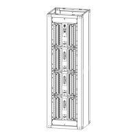
Figure 13 Cabinet Shipping Pallet ........................................................................................................... 20
Figure 14 Hardware Box Location............................................................................................................. 21
Figure 15 Footprint of Cabinets .............................................................................................................. 22