Page 21
© Copyright 2021 ABB. All rights reserved.
Mounting Hardware
Hardware for making all cabled connections is included with the BDFB. 3/8 inch hardware for Input
Load Bus connections is installed on the Load Shunt and Load Return Bus Details as shown in
section 9. CC408576210 ¼ inch conical nuts are provided for all output load and return connections.
These nuts are located in the hardware box as shown below.
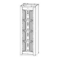
Floor Mounting
When installing the BDFB cabinet to the floor, the following mounting hardware may be required
depending on customer requirements.
• Drill anchor holes to depth specified in table below.
• Place floor insulation pad and/or use insulation bushings provided with anchors if required.
• Shim under cabinet corners as necessary to level.
• Torque anchors as specified in table below.
Seismic Zone Size
2”
deep
Table 3 Isolation and Leveling Kits
Ordering Code Description