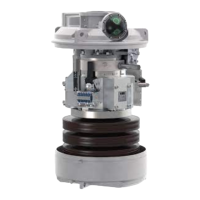
6. Link (E). Mount charging device on the spring mechanism. Adjust link (E) to
allow the trip free device to catch when the closing spring is about to be
nd
charged. Ensure that coupling is locked in 2 step of knife catch.
7. Complete operating gear. Mount the operating gears on frame with breaker
poles.
7.1 Charge the closing spring.
7.2 Close the breaker.
7.3 Charge the closing spring again. Check that clearance.
1. At upper trip free mechanism and knife catch is 0.8 - 1 mm.
This should be checked when spring is fully charged,
i.e. Before the link (E) is disconnected (immediately before
click noise).
7.4 If clearance is more than 1 mm then shorten the pull link (E), and if it
is less than 0.3 mm extend the link.
7.5 secure the lock nuts in link (E).
8. Lower trip free mechanism. Open the breaker and check the clearance (2).
Adjust clearance (2) to 1 mm by using dog point screw (B) on upper arm.
Secure the lock nut, when breaker is closed.
9. Micro-switches to be adjusted as per instruction IN 5452 0003 - 15.
10. Final test. Check breaker with operating circuit connected. While charging
at minimum operating voltage of motor the charging gear is supposed to
rotate until the coupling is locked by knife catch.
11. After 50 electrical operations, knee point setting (3), coupling clearance (1)
and cap clearance (2) should be checked and corrected, if necessary.
12. Seal various lock nuts of various setting with red point.
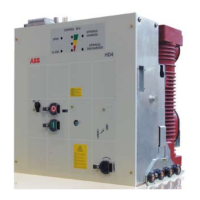
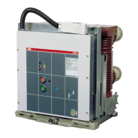
2.5 Accessories, spare parts and additional equipment
We recommend the following parts to be held as spare parts for the breaker unit
1 X Motor IN 4461 0002*
1 X Coil IN 5445 0007*
2 X Micro-switches IN 5445 0744 - A
1 X Breaker pole
(25)
 Loading...