6 Oil & gas application-specific considerations
Oil & gas application-specific considerations
The oil & gas market is the main user of Modbus guided-wave radar level transmitters. As such, specific
considerations are in order.
Mounting
• Avoid mounting the instrument's probe too close to the vessel inlet or to internal objects (15 cm [6 in]).
• If you suspect that the probe can come in contact with the nozzle, use a spacer.
Process
• Do not stack bushings to connect the coupler to the vessel (use 3-to-¾–inch NPT metal bushings
(order code A3) and 4-to-¾–inch NPT metal bushings (order code A4) on vessels with 3 in and 4 in
treaded connections.
• Ensure a good electrical connections between coupler and vessel (if metallic). Rust and corrosion
should be avoided.
– Limit the use of PTFE (Teflon™) tape as much as possible to keep a good electrical connection
between coupler, bushing and vessel.
• Avoid long nozzles (>61 cm [24 in]) (You can adjust the nozzle length in the Device Setup >
Application Setup > Nozzle Length menu).
• Avoid nozzles equipped with reducers (use of a coaxial probe is preferred in such cases).
• Avoid nozzles with a section extending inside the vessel. If it is impossible to avoid, 1) use a blocking
distance to account for all the potential ringing caused by the internal section of pipe or 2) check the
waveform for signal quality and, if still not acceptable, replace by a coaxial probe.
• For non-metallic vessels, mount the coupler on a metallic flange, a metal sheet (>15 cm [6 in] and
thick enough to support the instrument) or a 4-to-¾–inch bushing.
Changing the probe length
After changing the physical length of the probe, you must change the factory-set probe length
configured in the instrument (in the Device Setup > Application Setup > Probe Length menu).
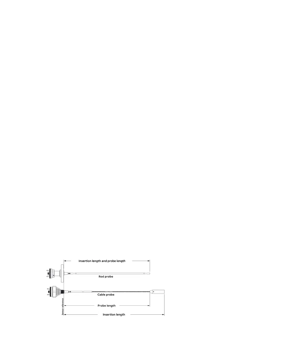
This procedure is explained in "Changing probe length" in the LWT300 User Guide. Probe length is the
distance between the sensor reference point and the top of the weight (see Figure 4 below).
—
Figure 4 Measuring the probe length

 Loading...


