LWT300 series (Modbus) Quick Start Guide 7
IMPORTANT: The probe length value entered must be accurate to <2.5 cm (1 in).
End of probe
• To improve performance and minimize the size of the dead zone, we recommend using the puck-
shaped weight (height: 2.5 cm [1 in], diameter: 7.3 cm [2 in]) (ABB order code QP6).
• Use "long" weights ONLY if the diameter of the vessel top opening does not allow you to use of the
puck-shaped version.
Configuring instrument for oil & gas applications
The following parameters need to be configured specifically for oil & gas applications. Configuration of
these parameters is explained in more detail in the LWT300 User Guide:
• Type of application (in the Easy Setup > Application Category menu) (see "Application Category"
on page 4 of this document).
– (If the application category selected is Interface (to measure the interface between liquids, e.g.,
oil on top of water), you must set the dielectric constant (DC) of the first liquid that the pulse will
encounter (in this case, oil) in the Device Setup > Sensor Setup > Upper Media DC menu (see
"Setting the dielectric constant of upper media" in the LWT300 User Guide). (Appendix D of the
LWT300 User Guide contains a list of dielectric constants for common substances).
• Calibration parameters (Empty/Zero, Full/Span, Level Offset) (in the Calibrate > Level > Level
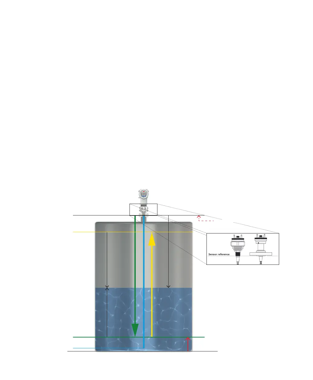
Calibration menu) (for details, see Figure 5 below.)
—
Figure 5 Calibration parameters
Full/Span
Empty/Zero
Probe length
Sensor
reference
Ullage
Level
Distance
Level offset
+ sensor offset

 Loading...


