LWT300 series (Modbus) Quick Start Guide 9
Finalizing the instrument setup
• It is considered good practice to use the Reset Tracking command after modifications have been
made to an instrument setup. This is performed in the Device Setup > Sensor Setup > Reset
Tracking menu where you select OK to perform the echo tracking reset.
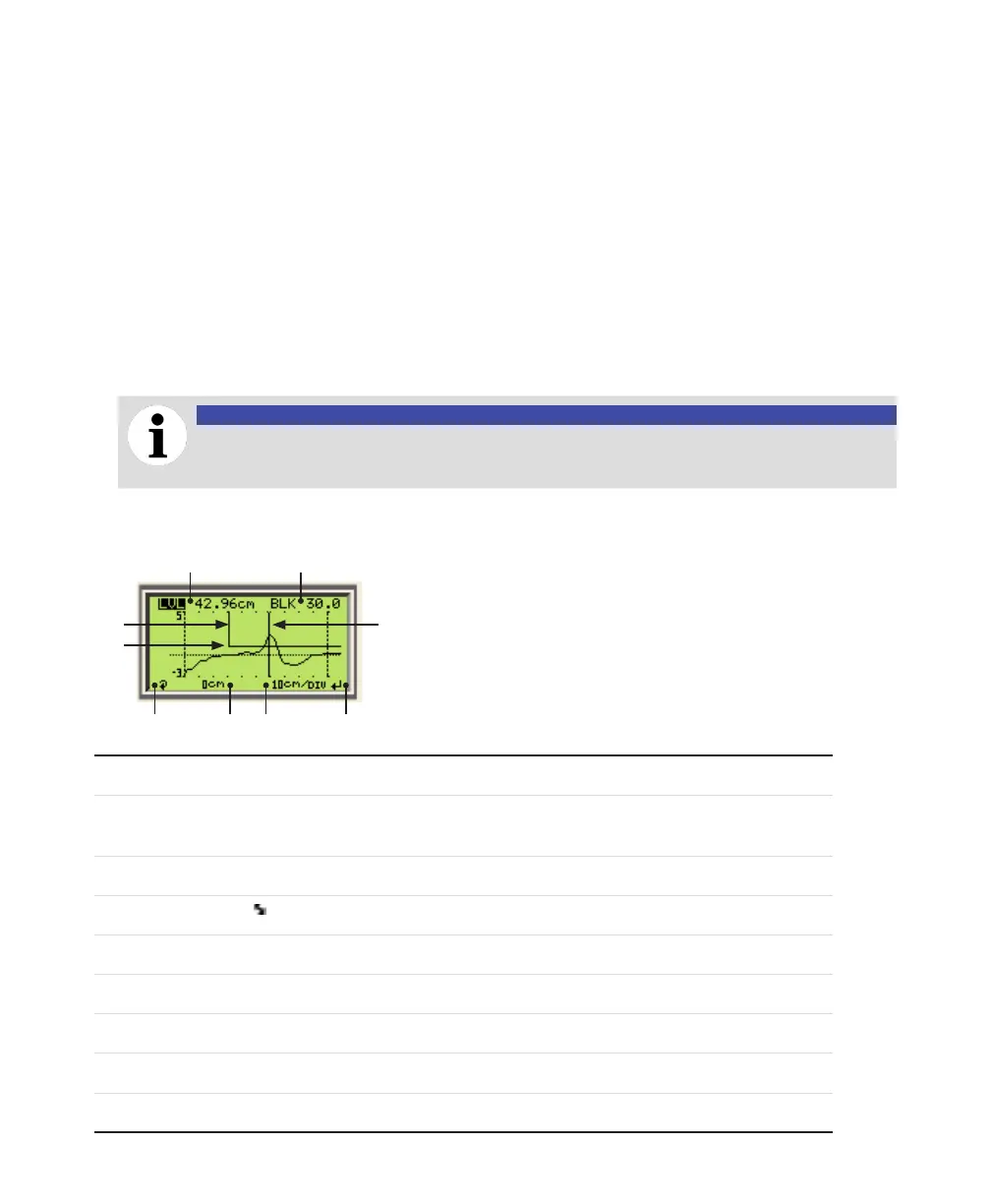
• At the end of the installation, it is also considered good practice to confirm proper installation by
taking a look at the generated waveform. Go to the Diagnostics > Waveform > At sensor Ref.
Point menu and check the quality of the waveform (see Figure 7 below; the waveform section close
to the reference point should not show ringing and the pulse at the level or interface distance should
be identified by the marker) (refer to "Diagnosing from a waveform" in the LWT300 User Guide).
• If you have emptied the vessel before installing the instrument, you should confirm the probe length
status (in the Diagnostics > Device Status > Probe Length Status menu) (refer to "Probe length"
in the LWT300 User Guide to make sure that the configured probe length is identical to the probe
length measured by the sensor.
NOTICE
Probe length confirmation can only be performed if the tank in which the probe is installed
is completely empty.
—
Figure 7 The waveform display
1
2
3
4567
8
1
Display of the level (LVL), distance (DIS), ullage (ULL) or interface (INT) value
2
Display of the blocking distance (BLK), safety distance (SFD), level amplitude threshold (LAT) or interface
amplitude threshold (IAT)
Note: This is the only highlighted option that is editable (see 4)
3
Level or interface marker
4
Exit (8 ) or Edit ( ) indicator
5
Zoom information
6
Reference distance
7
Display value selector
8
Level amplitude threshold (or Interface amplitude threshold, if INT is selected in 1) marker
9
Blocking distance (or safety distance, if SFD is selected in 2) marker
9

 Loading...


