Chapter 4 – Electrical Installation
Installation and Start-up Guide for NBRA-6xx 4-5
Power Connections
NBRA-653/663
WARNING! Before installation, switch off the mains supply to the
ACS 600. Wait five minutes to ensure that the intermediate circuit is
discharged. Switch off all dangerous voltages connected to the inputs
or the outputs of the ACS 600.
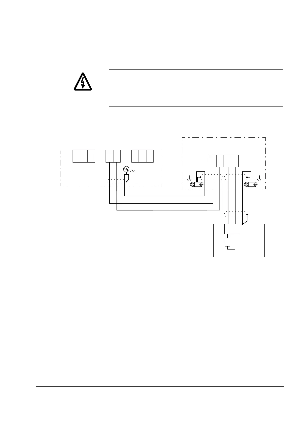
Figure 4-3 NBRA-653/663 power connections.
Notes on NBRA-653/663
Power Connections
If a cable with fine wire conductors is used, it is recommended to
terminate the conductors with cable ferrules. The ferrules are pressed
onto stripped conductor ends before inserting into terminals.
The tightening torque for the UDC+ and UDC– terminals of the
ACS 600 is 1.5 to 1.8 Nm. All other terminals are tightened
to 1 Nm. (For braking resistor terminal tightening torques, consult
resistor documentation.)
If more space for the installation work inside the chopper is required,
the front section of the bottom plate can also be removed. (Do not
remove the gland plate, ie. the rear bottom plate.)
ACS 600
U2 V2 W2U1 V1 W1
UDC+
UDC–
123
R
Braking Resistor
R–R+
PE
NBRA-6x3
R+ R–
UDC–
UDC+
312
12 3