Chapter 4 – Electrical Installation
Installation and Start-up Guide for NBRA-6xx 4-11
ACS 600 Connection Ensure that the UDC+ and UDC– busses of the chopper are properly
connected to the corresponding terminals of the ACS 600 (see Chapter
3 – Voltage Selection and Mechanical Installation).
Resistor Cable
Connection
Connections at the braking resistor:
(For terminal tightening torques, consult resistor documentation.)
• Twist the screen wires together and connect them to the earthing
terminal, along with conductor no. 3 (if present).
• Crimp cable lugs of appropriate size onto conductors 1 and 2.
• Connect conductor no. 1 to the R+ terminal.
• Connect conductor no. 2 to the R– terminal.
Connections at the braking chopper:
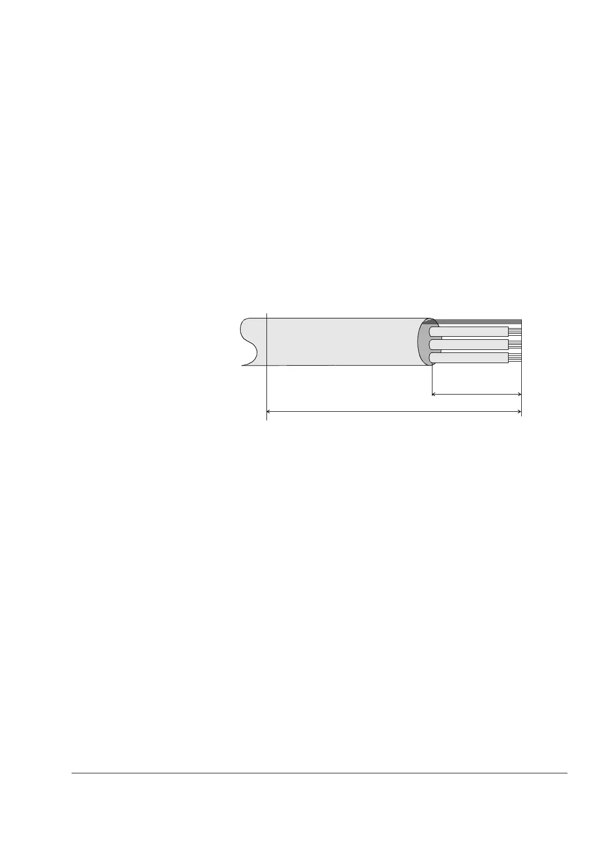
Figure 4-7 Resistor cable stripping diagram (braking chopper end).
All lengths are approximate and may vary according to the
cable lugs used.
• Cut and strip the cable as shown in Figure 4-7 above.
• Lead the cable through the cable entry into the converter unit.
• Slip the copper sleeve (inserted into the earthing clamp at the
factory) onto the outermost insulation of the cable so that insulation
and sleeve edges are aligned (see Figure 4-6).
• Bend the screen wires evenly backwards onto the copper sleeve.
• Unfasten the screen earthing clamp and slip it onto the screen wires
at the copper sleeve. Replace the clamp and tighten the fastening
screw to 3 Nm.
• Twist the screen wires together and connect to the earthing clamp
on the chopper as shown in Figure 4-6. Tighten the screws to 3 Nm.
• Connect conductor no. 3 (if present) to the earthing clamp on the
chopper (below the screen earthing clamp) as shown in Figure 4-6.
Tighten the screws to 3 Nm.
70 mm
190 mm
Gland Plate
Screen
1
3
2