Do you have a question about the ABB OVR-15 and is the answer not in the manual?
ABB's adherence to ISO 14001 standards for environmental management in production.
ABB's commitment to environmental protection and user's role in recycling.
Important warnings and cautions for safe operation and maintenance of the product.
Mandatory minimum procedures for safe work on LV cabinets.
Explanation of warning texts and symbols used in the manual and on the product.
Information on case markings and symbols for identifying and handling the product.
List of documents provided with the LV unit during dispatch.
Precautions and guidelines for safe transportation and lifting of the LV cabinet.
Procedures for checking the LV unit upon delivery for damage or discrepancies.
Guidelines for indoor storage of the LV cabinet to protect it from damage.
Procedures and precautions for safely lifting and moving the LV cabinet unit.
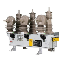
Description of the components and structure of the LV cabinet.
Overview of the low voltage control cabinet components and their functions.
Description of the battery charger's function in converting auxiliary power.
Requirements and connection details for the auxiliary power supply to operate the recloser.
Function of the ACM in regulating control signals for the recloser.
Details on the 12V battery bank providing backup power to the recloser.
Explanation of the selector switch modes for safe maintenance.
How to remotely monitor the availability of external auxiliary power.
Information on the microprocessor-based RER615 Intelligent Electronic Device.
Guidelines for proper grounding of the LV cabinet and associated components.
Procedure for connecting the HV and LV cabinets using the specified control cable.
Instructions for connecting the external auxiliary power supply to the control cabinet.
Mandatory checks to be performed before energizing the recloser on the main lines.
Mandatory steps before performing any maintenance on the recloser LV unit.
Procedure for safely removing the RER615 relay from its case.
Steps for safely removing the batteries from the LV unit.
Schematic illustrating the dual voltage sensing configuration.
Schematic illustrating the single side voltage sensing configuration.
Details and specifications found on the LV cabinet's rating plate.
Drawings showing the overall layout and components of the LV control cabinet.
Default parameters for monitoring circuit breaker conditions in the RER615.
Default settings for analog current input correction factors in RER615.
Default settings for analog voltage input correction factors in RER615.
Detailed table of settings for the RER615 relay applicable to OVR reclosers.
Information on battery self-discharge and storage recommendations.
Graph showing the relationship between terminal voltage and residual capacity.
| Nominal AC Voltage (Un) | 230 V |
|---|---|
| Maximum Continuous Operating Voltage (Uc) | 275 V |
| Number of Protected Poles | 1 |
| Rated Voltage | 230 V |
| Maximum Continuous Operating Voltage (MCOV) | 275 V |
| Voltage Protection Level (Up) at In | 1.5kV |
| Product Name | Surge Protective Device |
| Line Discharge Class | Type 2 |
| Standards | IEC 61643-11 / EN 61643-11 |