4NWP100559R0001_OPM_ABB_PVA31-11-T_10-20kVA_EN_140626 Page 22/37 ABB
Modifications reserved
5 OPERATION
This chapter describes how to operate the UPS through the LCD display.
WARNING!
ONLY PERSONS WHICH HAVE BEEN TRAINED BY SERVICE
TECHNICIANS OF THE SUPPLIER OR HIS AUTHORIZED SERVICE
PARTNERS ARE ALLOWED TO OPERATE THE CONTROL PANEL OF
THE UPS.
ALL OTHER INTERVENTIONS ON THE UPS SYSTEM HAVE TO BE
DONE ONLY BY SERVICE TECHNICIANS OF THE SUPPLIER.
The only user permitted operations are:
· Operate the LCD display
· Start up and shut down of the UPS of the user field (excluding the commissioning start up)
· Operation of additional SNMP adapters and their software
5.1 Control Panel
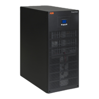
The user-friendly control panel is composed of LEDs, an LCD display and four selection keys.
Figure 18: Control Panel
5.1.1 LEDs
The LEDs gives the UPS mode or a faulty situation at a glance. The LEDs may blink or stay constantly
on depending on the UPS status. Table 3 indicates the meaning of each LED.
UPS status
(red)
Bypass mode / no power in output - - A D
Bypass mode / powered output - - B D
UPS is turning ON C C C C
Online mode B - - D
Battery mode B B - D
ECO mode B - B D
Battery test mode C C C C
Fault mode - - D B
Warning D D D A
Legend:
A: LED flashing
B: constantly lightened
C: lightened circularly
D: depends on the failure/warning
Table 3: LEDs indication
 Loading...
