11.
Connection of the communication and control signals
12.
Commissioning
13.
Instruments
PVI-6.0_8.0_10.0_12.5-TL-OUTD-Quick installation guide EN-RevB
EFFECTIVE 2014-03-06
© Copyright 2014 ABB. All Rights Reserved.
Specications subject to change without notice.
8.
Input connection (DC)
9.
Line cable and protection devices
10.
Output connection (AC)
14.
Structure of the display menu
15.
Characteristics and technical data
Contact us
www.abb.com/solarinverters
LEDs and BUTTONS, in various combinations, can be used to view the status or carry out complex actions that are described more fully in the manual.
060504
LED
POWER
GREEN On if the inverter is working correctly. Flashes when
checking the grid or if there is insufcient sunlight.
ESC It is used to access the main menu, to go back to the previous menu
or to go back to the previous digit to be edited
LED
ALARM
YELLOW The inverter has detected an anomaly. The anomaly
is shown on the display.
UP It is used to scroll up the menu options or to shift the numerical scale
in ascending order
LED
GFI
RED Ground fault on the DC side of the PV generator. The
error is shown on the display.
DOWN It is used to scroll down the menu options or to shift the numerical
scale in descending order
ENTER It can be used to conrm an action, to access the submenu for the
selected option (indicated by the > symbol) or to switch to the next
digit to be edited
ABB inverters are equipped with a graphic Display
05
, consisting of 2 lines of 16 characters each, which can be used to:
- Display the operating state of the inverter and the statistical data
- Display the service messages for the operator
- Display the alarm and fault messages for the operator
- Changing the settings of the inverter
During the normal operation of the inverter the display cycles through the GENERAL INFORMATION. This information relates to the input and output parame-
ters and the inverter identication parameters. By pressing ENTER it is possible to lock scrolling on a screen to be constantly displayed.
Press ESC to access the three main menus, which have the following functions:
- STATISTICS: Displays the statistics
- SETTINGS: Modify the settings of the inverter
- INFO: View service messages for the operator
Refer to the manual for details regarding use and functions available in the menu
Check for correct polarity in the input strings and absence of any leakage to ground in
the PV generator. When exposed to sunlight, the PV panels supply DC direct voltage to
the inverter.
The inside of the inverter may only be accessed after the equipment has been discon-
nected from the grid and from the photovoltaic generator.
Warning! The inverters to which this document relates to are WITHOUT ISOLATION
TRANSFORMER (transformer-less). This type involves the use of insulated photovoltaic
panels (IEC61730 Class A Rating) and the need to maintain the photovoltaic generator
oating with respect to earth: no pole of the generator must be connected to earth.
Each input is equipped with protection fuses on the -FS model: check that the fuse
current rating is the correct size for the photovoltaic modules installed.
For the string connections it is necessary to use the quick t connectors (multicontact or weidmüller)
located on the bottom of the mechanic
09
10
.
The number of quick t connectors changes based on the model of inverter.
STANDARD VERSION -FS VERSION -S VERSION
No. of input channels 2 2
No. of quick t connectors 12 (6 pairs) 8 (4 pairs)
- Crimp the Multicontact/Weidmüller MC4/WM4 quick t connector counterparts (supplied) to the string
cables or to the cables wired to the DC disconnect switches (external)
- Connect all the strings included in the design of the system and always check the tightness of the
connectors
- If some of the string inputs should not be used you must proceed to verify the presence of covers on
DC input connectors and then install them should they be absent: this operation is necessary for the
tightness of the inverter and to avoid damaging the free connector that could be used at a later date.
STANDARD VERSION
09 10
-S VERSION
09 10
-FS VERSION
09 10
Load protection breaker (AC disconnect switch) and line cable sizing
To protect the AC connection line of the inverter, we recommend installing a device for protection against over current and leakage with the following characteristics:
PVI-6.0-TL-OUTD PVI-8.0-TL-OUTD PVI-10.0-TL-OUTD PVI-12.5-TL-OUTD
Type Automatic circuit breaker with differential thermal magnetic protection
Nominal Voltage / Nominal Current 400 Vac / 16 A 400 Vac / 16 A 400 Vac / 20 A 400 Vac / 25 A
Magnetic protection characteristic B/C
Number of poles 3/4
Type of differential protection A/AC
Differential sensitivity 300 mA
ABB declares that the ABB transformerless inverters, in terms of their construction, do not inject continuous ground fault currents and therefore there is no requirement
that the differential protection installed downstream of the inverter be type B in accordance with IEC 60755 / A 2.
Characteristics and sizing of the line cable
For the connection of the inverter to the grid, you can choose between a star connection (3 phases + neutral) and a
delta connection (3 phases). The cross-section of the AC line conductor must be sized in order to prevent unwanted
disconnections of the inverter from the grid due to high impedance of the line that connects the inverter to the power
supply point.
Cross-section of the line
conductor
Maximum length of the line conductor
The values are calculated in nominal power condi-
tions, taking into account:
1. a power loss of not more than 1% along the line
2. copper cable, with HEPR rubber insulation, laid
in free air
PVI-6.0-TL PVI-8.0-TL PVI-10.0-TL PVI-12.5-TL
4 mm² 55 m 43 m 34 m 28 m*
6 mm² 80 m 65 m 51 m 42 m
10 mm² 135 m 108 m 85 m 70 m
16 mm² 210 m 173 m 136 m 113 m
* Up to 45 °C Ambient temperature
max 16 mm
19 ÷ 28 mm
2
Warning! Before performing any of the operations described below, ensure the AC line downstream the
inverter has been correctly disconnected
- Remove the protective lm located on the hole to be used for the AC cables
11
- Insert the M40 cable gland in the hole and secure it using the special M40 lock nut (supplied)
Warning! To ensure environmental protection IP65 it is necessary to x the cable gland to the inverter
chassis with a minimum tightening torque of 8.0 Nm
- Strip 10 mm of sheathing from the AC grid connection cables
- Plug the AC line cable into the inverter, passing it through the previously installed cable gland
- Connect the protective earth (yellow-green) cable to the contact labelled with the symbol on the terminal block
15
Warning! ABB inverters should be earthed (PE) via the terminal with the protective earth label , using a cable with an appropriate cross-
section of the conductor for the maximum ground fault current that the generating system might experience
- Connect the neutral cable (normally blue) to the terminal labelled with the letter N
- Connect the phase cables to the terminals labelled with the letters R, S and T
Warning! The AC cables must be tightened on the terminal block with a minimum torque of 1.5 Nm
Once the connection to the terminal board
15
is complete, screw in the cable gland rmly (tightening torque 5.0Nm) and check the tightness.
Each cable which must be connected to the connectors of the communication and control signals must pass through one of the ve service cable glands
12
.
An M20 cable gland (that takes cables from 7 mm to 13 mm in diameter) and a gasket with two holes to insert into the cable gland which enables two sepa-
rate cables of a maximum diameter of 5 mm to be accommodated, are available
Warning! To ensure environmental protection IP65 it is necessary to x the cable glands to the inverter chassis with a minimum tightening
torque of 7 Nm
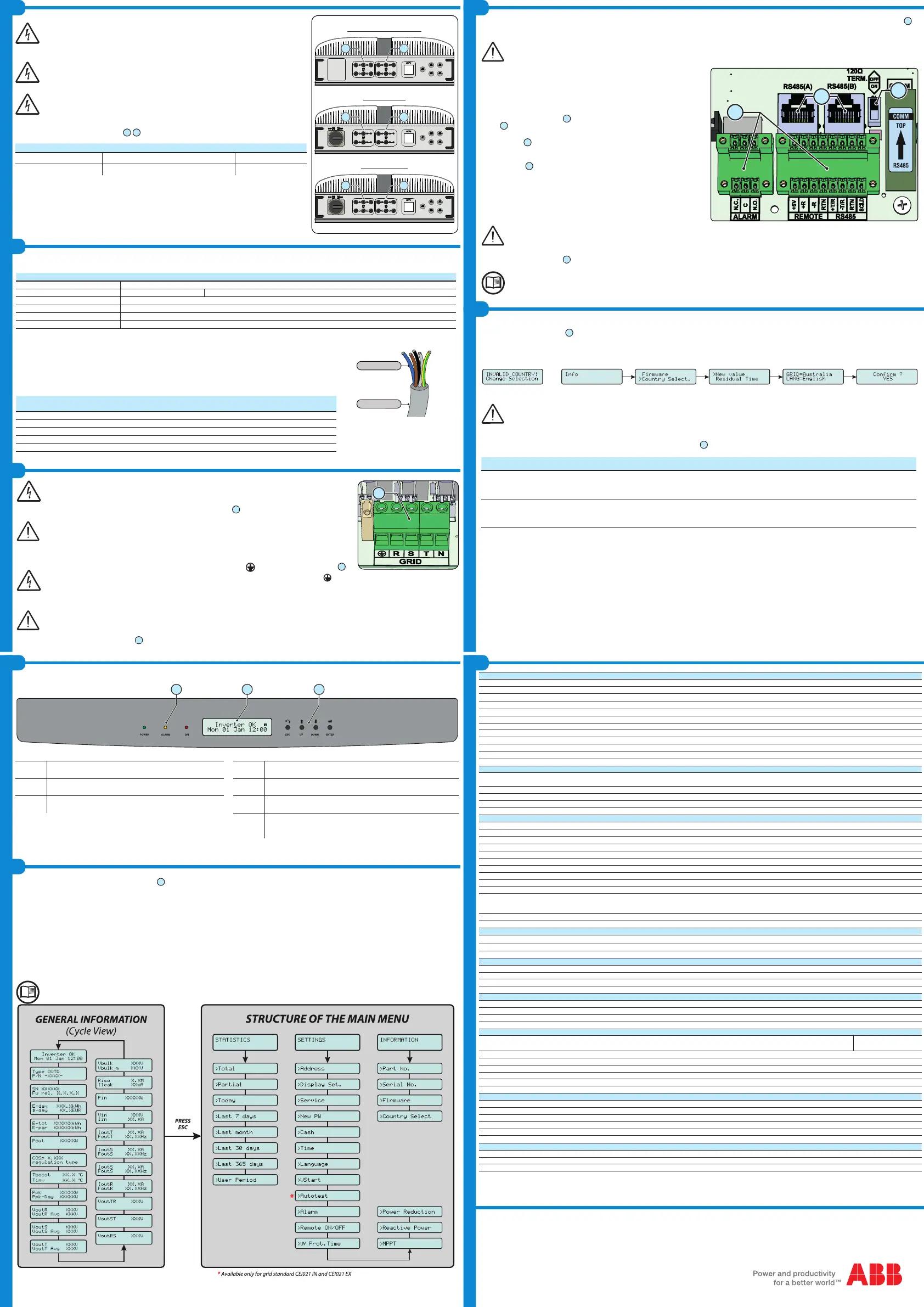
Connection to the RS485 communication line
The RS485 communication port is the inverter’s communication port. The
ABB inverters use an RS485 HALF-DUPLEX communication line made up of
two transmission and reception cables (+T/R and –T/R) and a communication
reference cable (RTN): all three cables must be connected in daisy-chain
conguration. The chain connection can be made without distinction by using
the RJ45 connector couples
19
(one for in and one for out) or the terminal
block
18
.The last inverter in the daisy chain must be “terminated” or the 120
Ohm communication line termination resistance must be activated by switching
the dip-switch
20
.
Using the alarm terminal block
Terminal block
18
connecting to the congurable relay that allows connection
of external devices which, according to the mode selected in the menu “SET-
TINGS > Alarm” can, for example, signal malfunctions. The operating modes
that can be set are: Production, Alarm, Alarm (Congurable) and Crepuscolar.
The ALARM contact can be used only with systems that ensure a safety isolating additional at least (supplementary insulation in relation
to the DC input voltage)
Using the REMOTE terminal block
The REMOTE terminal block
18
, if suitably congured, allows the “Remote ON/OFF” function to be used: this function allows remote disconnection of the
inverter from the grid
For further information regarding the conguration and use of the communication and control signals terminal block, please see the
manual
The inverter commissioning procedure is as follows:
- Switch the integrated switch
08
(versions –S and –FS) to the ON position or close the external switches: If the input voltage applied to one of the two input
channels is greater than the minimum starting voltage, the inverter will start up.
- When the inverter is turned on for the rst time you will be asked to select the “Country” of installation. This selection allows the inverter to automatically
congure its parameters to ensure that compliance with local standards; the default language corresponding to the selected “Country” will also be set.
Warning! After the grid standard was set you have 24 hours to make any changes to the grid standard value; 24 hours later the “Country
Select.” functionality will be blocked, and any subsequent changes can only be made using a password provided on request by ABB
- After you have set the “Country” value, the message “Inizializing...Please Wait” is displayed. Depending on the input voltage value, the inverter will show
various messages on the display and change the behaviour of the three LED
04
:
INPUT VOLTAGE DISPLAY MESSAGE LED STATUS DESCRIPTION
Vin < Vstart Waiting Sun
Green = FLASHING
Yellow = OFF
Red = OFF
The input voltage is not sufcient to permit connection to the grid.
Vin > Vstart Missing Grid
Green = FLASHING
Yellow = ON
Red = OFF
There is sufcient input voltage to permit connection to the grid:
the inverter waits until there is grid voltage to carry out the parallel
connection.
The inverter is powered ONLY by the voltage coming from the photovoltaic generator: presence of grid voltage alone IS NOT SUFFICIENT to permit
the inverter to start up.
- With the inverter in “Missing Grid” status, close the AC switch downstream the inverter so as to supply the grid voltage to the inverter: the inverter performs
the grid voltage check, measures the photovoltaic generator insulation resistance against earth and carries out other self-diagnosis checks. During the
checks before the parallel with the grid, the green LED keeps ashing, the others are off.
During the grid voltage check and measurement of the insulation resistance, the values for the grid voltage and frequency and the insulation resis-
tance measured by the inverter are shown on the display. The inverter completes parallel connection with the grid SOLELY if the grid parameters
meet the ranges provided for by the regulations in force and if the insulation resistance is greater than 1Mohm.
- If the preliminary checks for parallel connection to the grid are successful, the inverter connects to the grid and begins to export power to the grid. At this
stage, the display shows the inverter’s parameters in cycles. The green LED stays lit whereas the others are off.
PVI-6.0-TL-OUTD PVI-8.0-TL-OUTD PVI-10.0-TL-OUTD PVI-12.5-TL-OUTD
Input
Absolute Maximum Input Voltage (V
max,abs
) 900 V
Input Activation Voltage (V
start
) 360 V (adj. 250...500 V)
Input Operating Range (V
dcmin
...V
dcmax
) 0.7 x Vstart...850 V
Rated DC Input Power (P
dcr
) 6200 Wp 8250 Wp 10300 Wp 12800 Wp
Number of Independent MPPTs 2
Maximum Input Power for each MPPT (P
MPPT max
)
4200 W
5500 W 6500 W 8000 W
MPPT Input DC Voltage Range (V
MPPT min
,f ... V
MPPT max
,f) at P
acr
200...750 V
270...750 V 300...750 V 360...750 V
Maximum DC Input Current (I
dc max
) / for each MPPT (I
MPPT max
)
34.0 A / 17.0 A
34.0 A / 17.0 A 34.0 A / 17.0 A 36.0 A / 18.0 A
Maximum Input Short Circuit Current for each MPPT 22.0 A
Maximum Backfeed current (from AC to DC side) Negligible
Number of DC Inputs Pairs for each MPPT 2 (-S Version), 3 (Standard and -FS Version)
DC Connection Type Tool Free PV Connector WM / MC4
Input protection
Reverse Polarity Protection
Inverter protection only, from limited current source, for standard and -S versions, and for -FS version when
max 2 strings are connected
Input Overvoltage Protection for each MPPT - Varistor 2
Photovoltaic Array Isolation Control According to local standard
DC Switch Rating (-S Version) Max. 25.0 A / 1000 V
Fuse Rating (-FS Version) Max. 12.0 A / 1000 V
Output
AC Grid Connection Type Three phase 3W or 4W+PE
Rated AC Power (P
acr
)
6000 W
8000 W 10000 W 12500 W
Maximum AC Output Power (P
ac max
)
6600 W
(6)
8900 W
(1)
11000 W
(2)
13800 W
(3)
Rated AC Grid Voltage (V
acr
) 400 V
AC Voltage Range 320...480 Vac
(4)
Maximum AC Output Current (I
ac max
) 10.0 A 13.0 A 16.6 A 20.0 A
Inrush Current Negligible
Maximum Output Fault Current <25Arms (100mS)
Rated Output Frequency (f
r
) 50 Hz / 60 Hz
Output Frequency Range (f
min
...f
max
) 47...53 / 57...63 Hz
(5)
Nominal Power Factor (Cosphi
acr
)
>0.995 (adj. ± 0.9
with Pacr= 8.0 kW,
± 0.8 with max 6.67kVA)
>0.995 (adj. ± 0.9
with Pacr= 8.0 kW,
± 0.8 with max 8.9kVA)
>0.995 (adj. ± 0.9
with Pacr= 10.0 kW,
± 0.8 with max 11.5kVA)
>0.995 (adj. ± 0.9
with Pacr= 12.5 kW,
± 0.8 with max 13.8kVA)
Total Harmonic Distortion of Current < 2%
AC Connection Type Screw terminal block
Output protection
Anti-Islanding Protection According to local standard
Maximum AC Overcurrent Protection 12.0 A 15.0 A 19.0 A 22.0 A
Output Overvoltage Protection - Varistor 3, plus gas arrester
Operating performance
Maximum Efciency (η
max
)
97.6%
97.6% 97.8% 97.8%
Weighted Efciency (EURO/CEC)
96.5% /-
96.8% /- 97.1% /- 97.2% /-
Power Input Treshold 30.0 W
Stand-by Consumption < 10.0 W
Communication
Wired Local Monitoring PVI-USB-RS232_485 (opt.), PVI-DESKTOP (opt.)
Remote Monitoring PVI-AEC-EVO (opt.), VSN700 Data Logger(opt.)
Wireless Local Monitoring PVI-DESKTOP (opt.) with PVI-RADIOMODULE (opt.)
User Interface LCD Display with 16 characters x 2 line
Environmental
Ambient Temperature Range
-25...+60°C /-13...140°F
with derating above 55°C/131°F
-25...+60°C /-13...140°F with
derating above 50°C/122°F
Storage Temperature -40...80°C (-40...+176°F)
Relative Humidity 0...100% condensing
Environmental pollution classication for external environment 3
Noise Emission < 50 dB(A) @ 1 m
Maximum Operating Altitude without Derating 2000 m / 6560 ft
Environmental Category External
Physical
Environmental Protection Rating IP 65
Cooling Natural
Dimension (H x W x D) 716 x 645 x 224 mm / 28.2 x 25.4 x 8.8 inch
Weight <41 kg / 90.4 lb
Mounting System Wall bracket
Overvoltage Category in accordance with IEC 62109-1 II (DC input) III (AC output)
Safety
Isolation Level Transformerless (TL)
Safety Class I
Marking CE (50Hz only)
1. Limited to 8000 W for Germany
2. Limited to 10000 W for Belgium and Germany
3. Limited to 12500 W for Germany
4. The AC voltage range may vary depending on specic country grid standard
5. The Frequency range may vary depending on specic country grid standard
6. Limited to 6000 W for Germany
Remark. Features not specically listed in the present data sheet are not included in the product

 Loading...


