Do you have a question about the ABB Fimer PVI-10.0/12.5-TL-OUTD and is the answer not in the manual?
Details warranty terms and conditions for proper operation and adherence to manual.
Specifies items not provided with the equipment and clarifies manufacturer liability.
Provides a list of numbered references for components and features.
Illustrates component locations and connections using numbered references.
Outlines the necessary qualifications and skills for safe operation and maintenance.
Explains various symbols and signs used to indicate hazards and mandatory actions.
Defines the intended application, limitations, and general operating environment.
Lists actions strictly forbidden to ensure safety and maintain warranty.
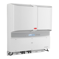
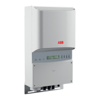
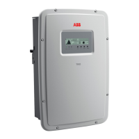
Details the different inverter models available and their distinguishing features.
Explains how to identify the inverter using labels and the manufacturer's information.
Presents detailed technical specifications, input/output parameters, and protection features.
Specifies required torque values for ensuring IP65 protection and optimal installation.
Provides the physical dimensions of the inverter unit including the wall bracket.
Details the specific dimensions and mounting points for the wall installation bracket.
Displays graphical representations of inverter efficiency at various operating conditions.
Explains automatic power reduction mechanisms due to thermal or electrical conditions.
Shows graphs illustrating power output reduction based on varying input voltage levels.
Explains the inverter's function of converting DC to AC power and feeding it to the grid.
Describes the integrated safety mechanisms for protecting the unit and users.
Provides essential safety guidelines and instructions for proper handling and operation.
Identifies hazardous areas and operations, emphasizing necessary precautions.
Details the importance of labels and signs on the equipment for hazard communication.
Warns about hot components and the risks associated with high temperatures.
Recommends appropriate personal protective equipment (PPE) for safe work.
Lists unavoidable risks and suggests remedies to mitigate them.
Provides guidance on safe methods for transporting and handling the equipment.
Offers recommendations for safe and proper lifting procedures for the inverter.
Outlines the procedure for safely unpacking and verifying the equipment's condition.
Enumerate all parts included in the inverter package for installation.
States the weight of the inverter for handling and installation planning.
Outlines general requirements and qualifications for proper equipment installation.
Details site preparation and environmental parameter checks before installation.
Addresses specific considerations and risks for installations at high altitudes.
Provides guidelines for selecting an optimal and safe location for the inverter.
Describes the step-by-step process for securely mounting the inverter on a wall.
Details essential pre-connection checks for the PV generator and system.
Explains how to configure the inverter's input channels for independent or parallel operation.
Details the procedure for connecting the PV generator to the inverter's DC inputs.
Describes the function and importance of string protection fuses in -FS models.
Provides detailed steps for correctly installing various types of quick-fit connectors.
Explains how to connect the inverter to the AC grid, including cable selection.
Recommends protection devices for the AC connection line and their characteristics.
Details the wiring process for connecting the AC output to the terminal block.
Explains the RS485 communication interface for monitoring and control.
Guides on setting up the RS485 communication for system monitoring.
Describes how to enable and manage remote on/off control functions.
Explains the function of the inverter's keyboard keys and LED indicators.
Details how the inverter provides operational data and how it can be transmitted.
Outlines the step-by-step process for initial setup and activation of the inverter.
Explains how to navigate menus and adjust various inverter operating parameters.
Provides a table detailing the meaning of different LED status combinations.
Explains the structure and content of the inverter's display menus.
Details how to access and interpret lifetime, partial, and daily production statistics.
Guides on accessing and modifying various inverter parameters via the settings menu.
Describes the procedure for running automated tests for grid compliance.
Recommends periodic checks to maintain the inverter's efficiency and performance.
Provides guidance on diagnosing and resolving common warning and error messages.
Lists and explains error and warning codes displayed by the inverter.
Details messages indicating output power limitations due to various conditions.
Explains the process to obtain a password for accessing advanced service settings.
Provides a step-by-step guide for safely replacing input fuses in the -FS model.
Details the procedure for replacing the internal buffer battery.
Explains how to check for ground leakage faults in the PV generator.
Guides on measuring insulation resistance to ensure system safety.
Outlines procedures and responsibilities for safely disposing of the equipment.


