56
1MRS750527-MUM
Feeder Terminal
Technical Reference Manual, General
REF 54_
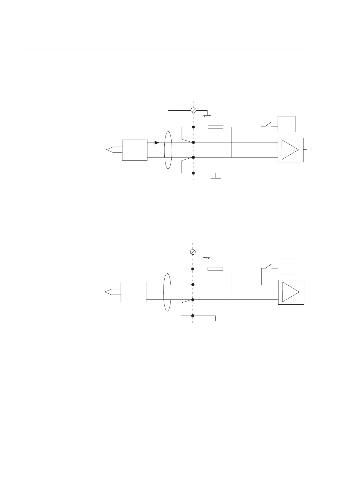
Current transducers
When a current transducer is connected to the RTD/analog input, the SHUNT and
IN+ terminals are linked together as are the GND and IN- terminals. The incoming
current signal is connected to the IN+ terminal and the outgoing current signal to the
IN- terminal.
currtran_b
Fig. 5.1.9.6.-2 Principle diagram for the connection of current transducers
Voltage transducers
When a voltage transducer is connected to the RTD/analog input, the GND and IN-
terminals are linked together. The incoming voltage signal is connected to the IN+
terminal and the return voltage signal lead to the IN- terminal.
volttran_b
Fig. 5.1.9.6.-3 Principle diagram for the connection of voltage transducers
*) The GND terminals are galvanically isolated from the supply and enclosure of the
feeder terminal, but they are all connected to each other, that is, they share the same
potential. When several inputs are connected to single-ended signal sources that
share a common ground, ground loops result if the connection GND <-> IN- is done
on every input. In this situation, the connection GND <-> IN- is done on only one of
the concerned RTD/analog inputs.
SHUNT
IN -
GND
I
*)
IN +
G
mA
DIFF
+
-
Transducer
amplifier
Sensor
SHUNT
IN -
GND
*)
IN +
G
mA
DIFF
+
-
Transducer
amplifier
Sensor