I.L. 40-386.12
1-4
1
hardware, it is possible to perform all relay setting and data interactions that are possible from
the man-machine interface. RCP is
required
to communicate with the REL301/302 via the com-
munication port(s). Refer to RCP instruction manual, I.L. 40-603, for detailed information.
1.6.1 ABB Bulletin Board
The ABB Relay Division Bulletin Board (BBS) is now on line. To obtain the latest version of RCP
software, please call the ABB BBS via modem at:
(800) 338-0581 or (954) 755-3250
Using configuration settings 300-14,400 bits/second, 8 data bits, 1 stop bit, no parity and full du-
plex. Once the connection is established and login is completed, choose L - Library of Files from
the TOP menu. Next, select D - Down Load File, from the Library of Files, RCPxxx.EXE (where
xxx is the most recent version number e.g. 180 for version 1.80). RCPxxx.EXE is a compressed,
self extracting file which is expanded and installed by simply typing RCPxxx and following the
instructions. RCP Version 1.82 required to interact with Reclosing firmware Version 1.20.
1.7 Synchronism Check Option
REL 301/302 reclosing option can be
supplied with internal synchronism
check and voltage check, Hot Bus
Dead Line (HBDL) or Hot Line Dead
Bus (HLDB), logic. For relays supplied
with internal synchronism checking
logic, supervision of REL 301/302 re-
closing is settable for synchronism
and/or HBDL and/or HLDB for each
reclosing attempt.
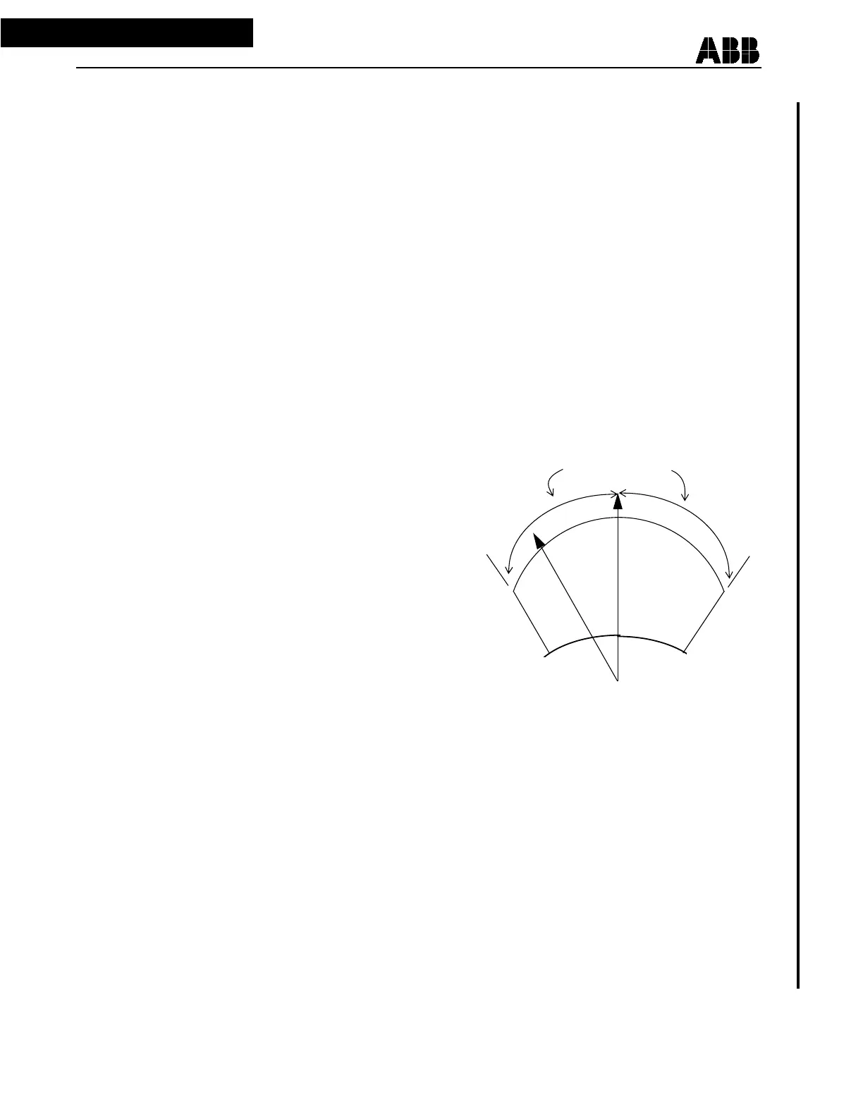
REL 301/302 reclosing option syn-
chronism checking logic utilizes a
“windshield wiper” characteristic (see
Figure 1-2). This is, a combination of
synchronism voltage, magnitude mea-
surement and voltage angle difference
measurement. Both magnitude and
angle difference measurement must
be within the user’s set range to pro-
duce synchronism check permission
of reclosing.
1.7.1
Application (120 volt Synchronism Input)
The REL 301/302 has an option to accept a phase to phase voltage input for the “Line” Voltage
input. The “Line” Voltage inputs VS (FT-10, polarity) and VSR (FT-9, non-polarity), with this op-
tion, is from a phase to phase connected potential device with a 120 volt secondary voltage rep-
resentation of the primary phase to phase voltage. The “Bus” voltage reference is from the relay
protection, voltages V
A
, V
B
or V
C
, (FT-1, FT-2, and FT-3 respectively) and is selected by
choosing the appropriate reference with jumper P12 on the Filter module. (See I. L.40-386.1 Fig-
ure 5-1 for jumper location). The appropriate reference is chosen by observing the polarity
Sync-Angle
WINDSHIELD WIPER CHARACTERISTIC
VMAX
V
Line
V
Bus
Figure 1-2
HOT
DEAD
VMIN
 Loading...