I.L. 40-386.12
2-19
2
This completes the basic acceptance test for the REL 301/302 Recloser with Synch-check
option.
2. 11 DETAILED EVALUATION TESTS SYNCHRONISM/VOLTAGE CHECK OPTION WITH BREAKER
EMULATION
a.1 Check of Reclose Sequence with HBDL
Condition. Apply and/or verify settings in Ta-
bles 2-7 and 2-8. Apply a voltage above the
setting value of “VMax” to the Bus voltage input
and a voltage below “VMin” to the Line voltage
input. Repeat the test in Paragraph 2.8, Sec-
tion c.2 above. Reclosure 1 should be
successfully completed since the voltage
check condition is satisfied and the “HBDL”
LED should be lit as verification. Note that a
“Sync Time” timer count down occurs in addi-
tion to the “Reset” timer count down. “Sync
Time” is the minimum amount of time the volt-
age check condition must be satisfied before
the “Reset” timer count down can begin.
a.2 Check of Reclose Sequence with HLDB
Condition. Apply a voltage above “VMax” to
the Line voltage input and below “VMin” volt-
age to the Bus voltage input. Repeat the test in
Paragraph 2.8, Section c.4. Reclosure 2
should be successfully completed since the
voltage check condition is satisfied and the
HLDB LED should be lit as verification. Note
that a “Sync Time” timer count down occurs in addition to the “Reset” timer count
down.
a.3 Check of Reclose Sequence with Synchronism Check Condition. Apply a volt-
age above “VMax” to both the Bus and Line voltage inputs. The angle between the
two voltages must be less than the “Sync Angle” setting. Repeat the test in Para-
graph 2.8, Section c.2.. Reclosure 1 should be successfully completed since the
synchronism check condition is satisfied and the SYNCHRONISM LED should be lit
as verification. Note that a “Sync Time” timer count down occurs in addition to the
“Reset” timer count down.
Change the “Recl 1” setting to “52b only” and return to “READY” by pressing the RE-
SET push-button.
a.4 Check of Reclose Sequence without HBDL or HLDB Condition. Change the
“Recl1 Sync” and the “Recl2 Sync” settings to “No” and return to “READY” by press-
ing the RESET push-button. Apply a voltage above the setting value of “VMax” to
both the Bus voltage and Line voltage inputs. Repeat the test in Paragraph 2.8, Sec-
tion c.2. “Reclosure 1” will not be successfully completed since neither voltage check
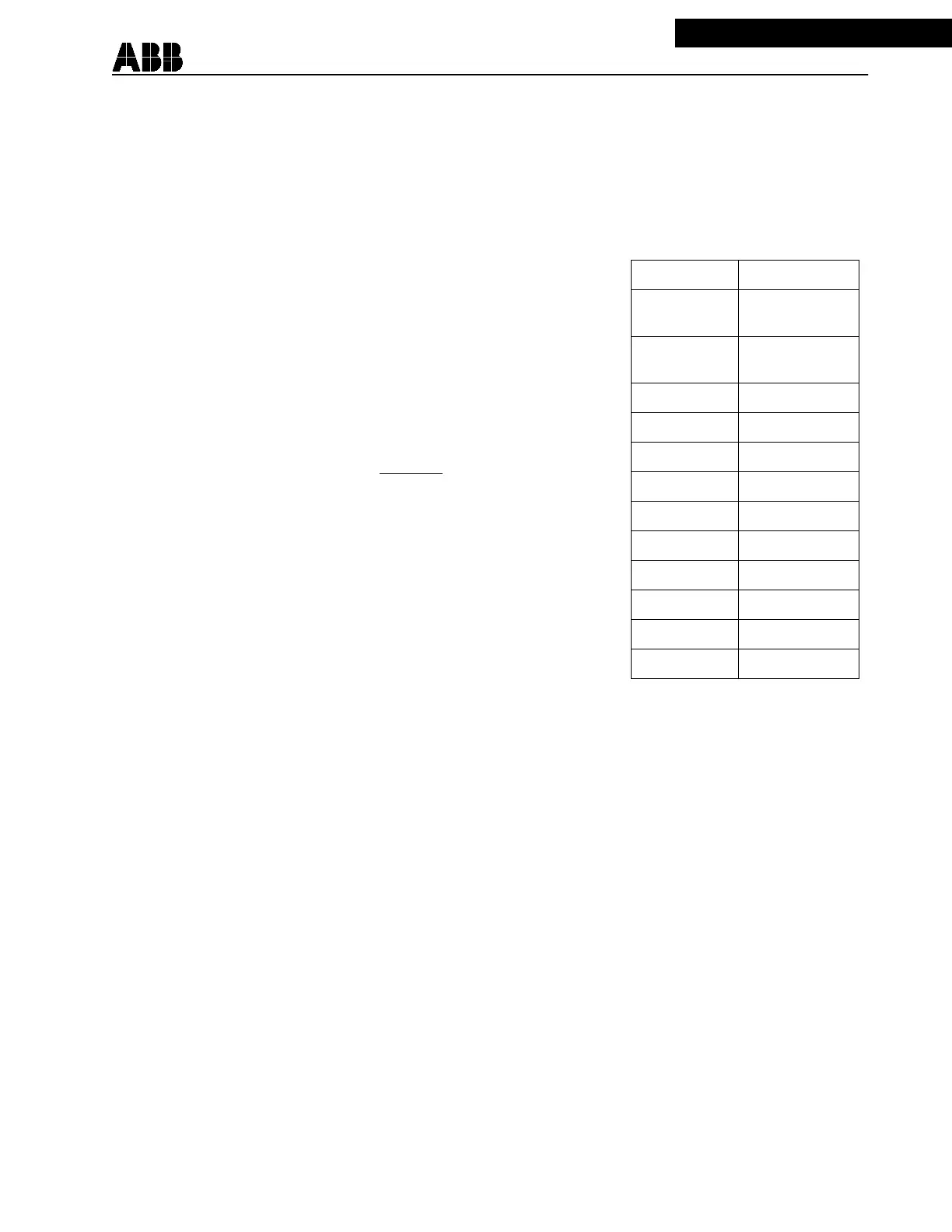
Table 2-8:
Test Settings
Sync Set ? Yes
V Max 53 Volts
90 Volts (120 V)
V MIn 13 Volts
22 Volts (120 V)
Sync Angle 20
o
Sync Time 2.0 sec
Recl1 HLDB Yes
Recl1 HBDL Yes
Recl1 Sync No
Recl1 Wait 60 sec
Recl2 HLDB Yes
Recl2 HBDL Yes
Recl2 Sync No
Rec2 Wait No Time Limit
 Loading...