IEC06000505 V1 EN-US
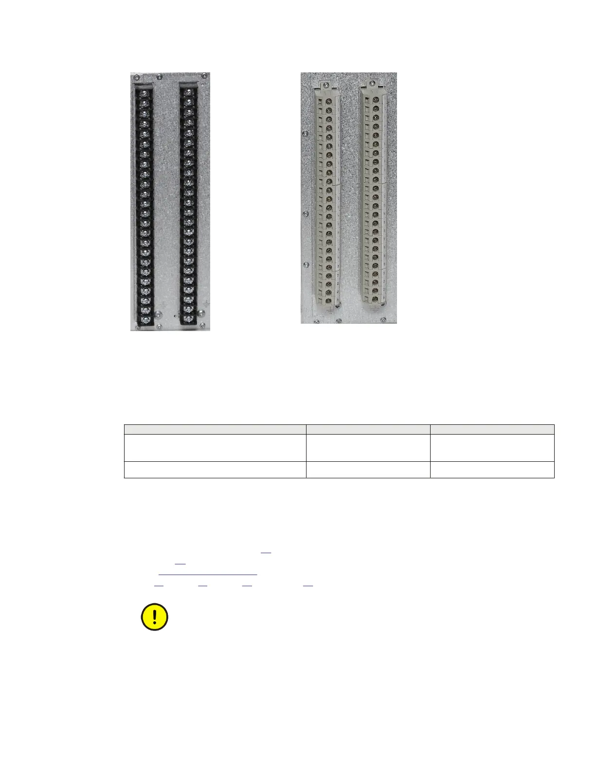
Figure 27: Examples of ringlug
terminals
IEC06000506 V1 EN-US
Figure 28: Examples of standard
compression connection
terminals
SEMOD53376-2 v6
Table 9: CT and VT circuit connectors
Connector type Rated voltage and current Maximum conductor area
Screw compression type 250 V AC, 20 A
4 mm
2
(AWG12)
2 x 2.5 mm
2
(2 x AWG14)
Terminal blocks suitable for ring lug terminals 250 V AC, 20 A
4 mm
2
(AWG12)
6.1.5 Connecting the binary input and output signals
M11992-9 v8
Auxiliary power and signals are connected using voltage connectors. Signal wires are connected to
a female connector (see Figure 29) which is then plugged into the corresponding male connector
(see Figure
30) located at the rear of the IED. For location of BIM, BOM, SOM and IOM refer to
section "Rear side connectors". Connection diagrams for BIM, BOM, SOM and IOM are shown in
Figure
17, Figure 21, Figure 22 and Figure 23.
Do not insert anything else to the female connector but the corresponding male
connector. Inserting anything else (such as a measurement probe) may violate the
female connector and prevent a proper electrical contact between the printed
circuit board and the external wiring connected to the screw terminal block.
1MRK 514 026-UUS F Section 6
Connecting
670 series 49
Installation manual
 Loading...


