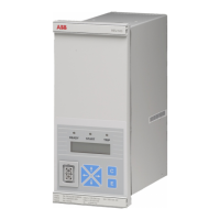
Combined overvoltage and undervoltage
relay
REU 523
1MRS 751123-MBG
2
Application The over and undervoltage relay REU 523 is
a secondary relay which is connected to the
voltage transformers of the object to be pro-
tected. The over and the undervoltage unit
continuously measure the fundamental wave
of the phase-to-phase voltages of the object.
On detection of a fault, the relay will start,
trip the circuit breaker, provide alarms, record
fault data, etc., in accordance with the appli-
cation and the configured relay functions.
The overvoltage unit includes low-set stage
U> and high-set stage U>> and the undervolt-
age unit low-set stage U< and high-set stage
U<<. The high-set undervoltage stage can
alternatively be set to evaluate the positive-
phase-sequence voltage. In addition, the high-
set undervoltage stage can be configured to
evaluate only one instead of three phase-to-
phase voltages.
The protection functions are independent of
each other and have their own setting groups
and data recordings. The over and undervolt-
age functions use conventional voltage trans-
former measurement.
An output contact matrix allows start or trip
signals from the protection stages to be
routed to the desired output contact.
Design The relay includes a high-set and low-set
overvoltage unit, a high-set and low-set und-
ervoltage unit and a circuit-breaker failure
protection unit. Further, the relay includes an
HMI module, a self-supervision system and a
disturbance recorder.
Overvoltage unit
When the voltage values exceed the set start
value of low-set stage U>, the overvoltage
unit will start to deliver a start signal after a
~60 ms’ start time. When the set operate time
at definite-time characteristic or the calcu-
lated operate time at inverse definite mini-
mum time (IDMT) characteristic elapses, the
overvoltage unit will deliver a trip signal.
When the voltage values exceed the set start
value of high-set stage U>>, the overvoltage
unit will start to deliver a start signal after a
~50 ms’ start time. When the set operate time
at definite-time characteristic or the calcu-
lated operate time at IDMT characteristic
elapses, the overvoltage unit will deliver a
trip signal.
The low-set and the high-set stage of the
overvoltage unit can be given either a defi-
nite-time or an IDMT characteristic. At
IDMT characteristic, two time/voltage curve
groups, A and B, are available.
It is possible to block the tripping of an over-
voltage stage by applying an external binary
input signal to the relay.
The high-set stage can be set out of operation.
This state will be indicated by dashes on the
LCD and by “999” when the set start value is
read via serial communication.
Undervoltage unit
When the voltage values fall below the set
start value of low-set stage U<, the undervolt-
age unit will start to deliver a start signal after
a ~ 80 ms’ start time. When the set operate
time at definite-time characteristic or the cal-
culated operate time at IDMT characteristic
elapses, the undervoltage unit will deliver a
trip signal.
The high-set undervoltage stage, U<<, can be
set to start and trip either based on conven-
tional undervoltage measurement or on the
calculated positive-phase-sequence voltage,
U
1s
. Selecting either of these two will auto-
matically deseclect the other.
When the conventional protection mode has
been selected and the voltage values fall
below the set start value of the high-set stage,
the undervoltage unit will start to deliver a
start signal after a ~50 ms’ start time.
When the positive-phase-sequence protec-
tion mode has been selected and the calcu-
lated positive-phase-sequence voltage value,
U
1s
, falls below the set start value of the high-
set stage, the undervoltage unit will start to
deliver a start signal after a ~50 ms’ start
time. When the set operate time at definite-
time characteristic or the calculated operate
time at IDMT characteristic elapses, the und-
ervoltage unit will deliver a trip signal.
The low-set and the high-set stage of the und-
ervoltage unit can be given either a definite-
time or an IDMT characteristic. At IDMT
characteristic, one time/voltage curve group,
C, is available.
The start and the tripping of an undervoltage
stage can be set to be internally blocked when
the measured value falls below 0.2 x U
n
. In

 Loading...