18
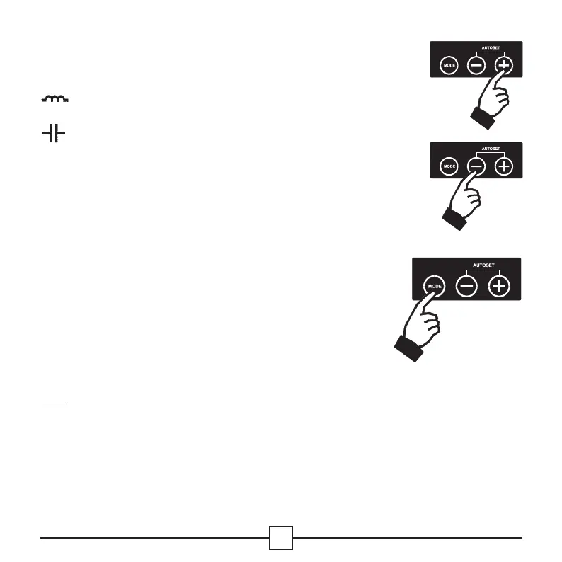
Step 5. Set your target cos
ϕ
by pressing
either the - or + button.
indicates an inductive PF and
iindicates a capacitive PF.
Step 6. Reactivate the AUTO Mode by using
the Mode button repeatedly.
During this procedure, the values of the parameters
automatically set in the previous step will be displayed.
All parameters are also programmable manually (see
chapter 11).
Once in AUTO Mode, the RVC automatically switches on the
necessary steps to reach the programmed target cos
ϕ
.
The actual cos
ϕ
appears on the LCD display.
Note
: a negative cos
ϕ
indicates that the load is re-injecting
reactive power on the network. The RVC continues to work
normally.