11
NETWORK SUPPLY
LOAD
M1
L1
L2 L3 k l
l
L2
L3
M2
1A 2 3 4 5 6 7 8 9 10 11 12
6
mm
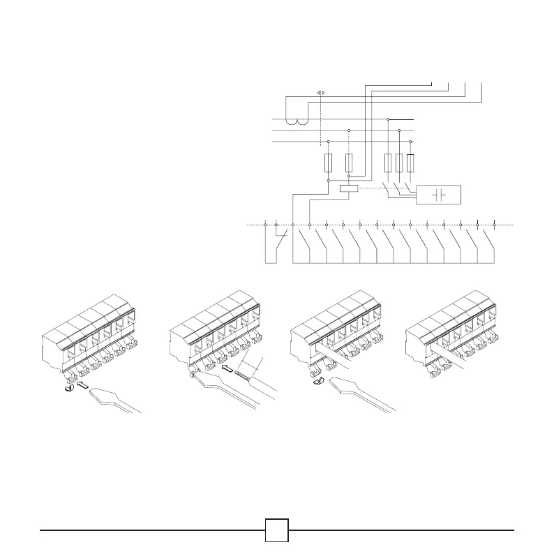
4. Connection arrangement
Wiring diagram
k, l: leads of the current transformer
L2, L3: 2 of the 3 phases
(not monitored by the CT)
M1, M2: leads of the normally closed
contact
A: output relay common source
1-12: outputs
Leads connection
1. Push the lever of
the connector
backwards with a
screwdriver.
2. Insert the wire in
the corresponding
connection hole
while keeping the
pressure on the
lever.
3. Release the
screwdriver.
4. The wire is
properly connected.
1234