20
Terminals
and wiring
The screw terminal to facilitate all input and
output connections are located on the rear panel
of the annunciator case. Each screw terminal
can accommodate one or two max. 2.5 mm
2
wires. No terminal lugs are needed.
A connection diagram is attached to on one of
the side surfaces of the annunciator case.
SACO 16D1
Made in Finland
12 11 10 9 8 7 6 5 4 3 2 1
24 23 22 21 20 19 18 17 16 15 14 13
60 59 58 57 56 55 54 53 52 51 50 49
72 71 70 69 68 67 66 65 64 63 62 61
L
+
N
–
L
+
N
–
U
N
=18…80V
U
N
=80…265V ~
RS 811163-BA
RS 811163-AA
SERIAL NO
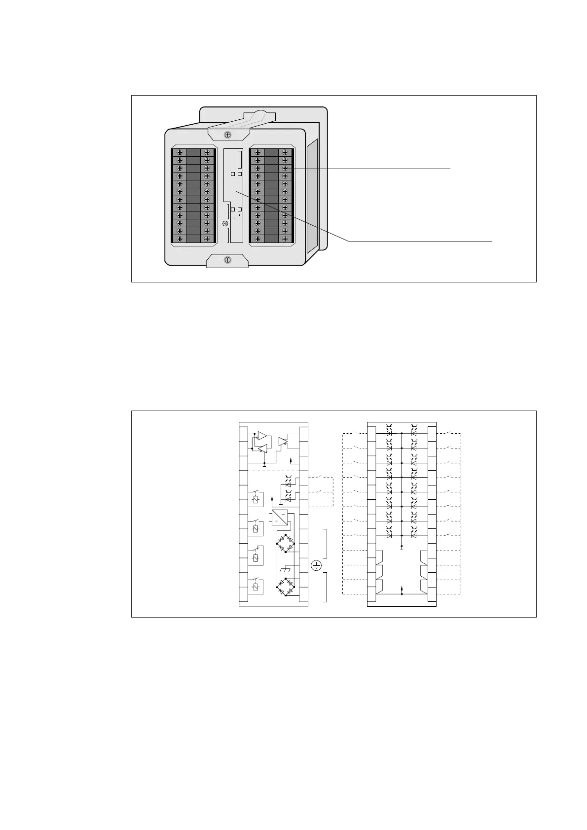
Fig. 20. Rear view of the annunciator unit SACO 16D1.
Connections:
Auxiliary supply 20-24
Protective ground 22
Field contact circuits 49 - 72
Acknowledge/reset 16 - 18
Reflash outputs 5 - 12
Serial interface 1 -3 and 13 - 14
Fig. 21. Connection diagram for the annunciator unit SACO 16D1.
Important 1
Make sure that the connected auxiliary supply
voltage complies with the specification. If two
auxiliary supply voltages are used, both voltages
are to be in accordance with the specified supply
voltage range.
Also make sure that the Protective ground (22)
is properly wired.
Important 2
If the annunciator is powered from two separate
auxiliary voltage sources, the supply networks
must be galvanically separated e.g. with an iso-
lating transformer if the customer does not
accept that the supply networks are galvanically
interconnected.
72
71 70 69 68 67 66 65 64 63 62 61
60
59 58 57 56 55 54 53 52 51 50 49
CH1
CH11
CH9
CH10
CH12
CH13
CH14
CH15
CH16
CH2
CH3
CH4
CH5
CH6
CH7
CH8
24
23 22 21 20 19 18 17 16 15 14 13
12
1110987654321
+48V
Rx/Tx
SIGNAL
GND
GROUP
AL. 1
+
-
RTS
FOR
SPA-ZC
+
-
N -
L +
N -
L +
RESET
AUD.
RESET
GROUP
AL. 2
AUD.
ALARM
FAULT
+48V
+8V
Numbered terminals
Ratings, i.e. type designation,
serial number and the specified
auxiliary supply voltage range
which has been indicated with
a cross in a square