29
Selection of field
contact type or
pulse counter
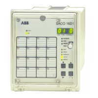
The LED marked INPUT is called up with the
parameter selector push-button ↓ and the chan-
nel to be programmed is chosen with the chan-
nel selector push-button ∩. The cursor is moved
to the third digit from the left of the display with
the cursor control push-button →. The value
corresponds to the following input signal types:
0 = input signal from a normally open field
contact
1 = input signal from a normally closed field
contact
2 = channel activated from a raising edge signal
only
3 = channel activated from a falling edge signal
only
4 = channel activated from a raising and falling
edge signal
5 = Pulse counting on closing contact
6 = Pulse counting on opening contact
7 = Pulse counting on closing and opening con-
tact
The chosen value is selected with the data value
selector push-button ↓ and stored in the param-
eter memory with the enter command push-
button.
NOTE!
Those channels which have been programmed
to be activated by a raising or a falling edge signal
are not to be linked to any other type of reflash
group than to the AACR and ISR types. A
channel which is controlled by an edge signal
can be interlocked but it can not itself generate
an interlocking signal to be forwarded.
Selection of
channel-specified
indications
The LED marked INPUT is called up with the
parameter selector push-button ↓ and the chan-
nel to be programmed is chosen with the chan-
nel selector push-button ∩. The cursor is moved
to the fourth digit from the left with the cursor
control push-button →. The fourth digit ex-
presses the type of indication as follows:
0 = normal sequence, i.e. the same operation
sequence that has been selected for the whole
annunciator unit (se section Selection of
alarm sequence type on page 31)
1 = normal sequence, i.e. the same operation
sequence as has been selected for the whole
annunciator unit but extended with an audi-
ble ringback feature upon return to normal
of an alarm channel. Applies only to the
sequences 3 (ISA R-1) and 4 (DIN 19235),
2 = field contact following indication without
audible alarm
The chosen value is selected with the data value
selector push-button - and stored in the param-
eter memory with the enter command push-
button.
Configuration
of pumping
supervision
The LED marked INPUT is called up with the
parameter selector push-button ↓ and the chan-
nel to be included in the pumping supervision is
chosen with the channel selector push-button
∩. The cursor control push-button → is pressed
five (5) times and the first, third and fourth
digits are lit. The third and fourth digit expresses
the pumping supervision as follows:
00 = pumping supervision not in use
01...99 = maximum allowed events per minute
Configuration of
reflash group alarms
The LED marked GROUP is called up with the
parameter selector push-button ↓ and the chan-
nel which is to be joined to a reflash group is
selected with the channel selector push-button
∩. Then with the cursor control push-button
→ the cursor is moved to the first two digits
from the left corresponding to channel reflash
type A or to the last two digits corresponding
to the channel reflash type B. The designated
reflash group is selected with the data value
selector push-button ↑, that is:
01 = output reflash group 1
02 = output reflash group 2
If required the channel reflash types A and B can
both be programmed for the same channel. The
selected reflash configuration is stored in the
program memory using the enter command
push-button.