abb
SafeLink
SF
6
Insulated Ring Main Unit
Installation and Operating Instructions
SLMIO ver 2.12 ABB Ltd, Switchgear Division, Auckland, New Zealand 6
2 Operation
The following sections describe the operating procedure for SafeLink. There are no
parts within the SafeLink unit that require user attention other than the fuses and the gas
density gauge.
Equipment suffering faults or damage must be returned to
your supplier for servicing.
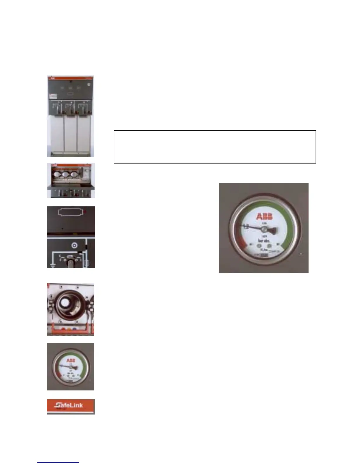
Ensure the gauge reads in the green area before switching.
2.1 Gas Density Gauge
During operation, the gas density of the
SafeLink unit should be maintained in
the green region. The gas pressure has
been factory set to 1.2bar absolute (at
20°C). Each switch is filled with
approximately 1kg of SF
6
gas.
The gas density gauge differs from a
simple pressure indicator in that it is
temperature compensated, thus giving
accurate and reliable information
wherever the SafeLink is installed.
All units are tested for gas tightness
during production to ensure any gas
leakage rate is less than 0.5% per annum
(maximum 3 × 10
-6
mbarl/s using helium).
In rare circumstances, the SafeLink unit may need to be topped up with SF
6
gas (for
instance to replace gas removed for sampling purposes). Gas filling is through a valve at
the front of the unit. See section 3.3 on page 12 for further details.
2.2 General Switch Operation
All switches (ring and fuse) have the same basic operating procedure. Select the
operation desired with the rotary selector. The spring-loaded selector must engage with
the location hole in the panel. Symbols to the right and left of the handle hole indicate
the operations possible in the respective positions.
Access for the operating handle is controlled by a rotary selector that has one of three
possible states:
1. Handle access blocked; no switching possible.
2. Switch able to operate from off to on (and vice versa)
3. Switch able to operate from earth to off (and vice versa).
The selector can be padlocked in any of these three positions.
From off status, selection of either earth or main switch operation is possible. From on
Figure 5: SafeLink gas density gauge.

 Loading...


