26 SCC-C Sample Gas Cooler Operator’s Manual 42/23-55 EN Rev. 1
Description, continued
Condensate Removal The condensate that accumulates comes out via the condensate nozzle on the
heat exchanger 5 (see Fig. 8).
The condensate is removed automatically by the peristaltic pump, which is
incorporated as an optional extra.
Sample Gas Outlet
Temperature
Measurement and
Display
The measuring gas outlet temperature is measured using the Pt-100 temperature
sensor in the cooling block 7 of the sample gas cooler, and displayed in digital
form in °C on temperature controller 9 (see Fig. 8). The sample gas outlet tempera-
ture is set in the factory to +3 °C.
Sample Gas Outlet
Temperature
Monitoring
The temperature controller sends out a status signal if the temperature rises
above/falls below the respective limit values of +3 °C ± 3 °C as set up in the
factory. This signal is present at a floating change-over contact that is rated up to
250 V AC/2 A.
Set Point Adjustment The set point for the sample gas outlet temperature can be set at the temperature
controller:
Press key P; the set point is displayed. Use arrow keys to adjust the set point.
Press key P; the new set point is stored.
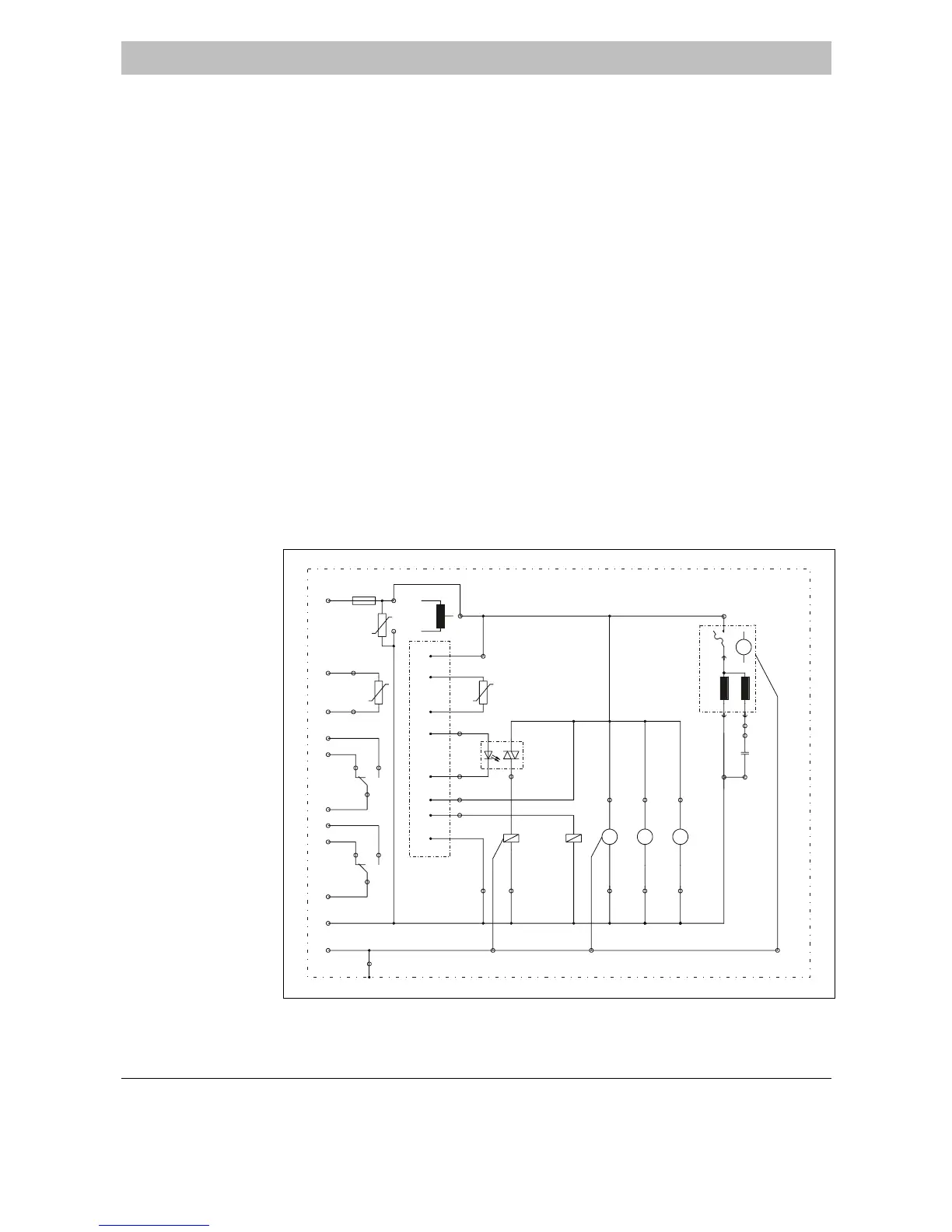
Fig. 9
Circuit Diagram
X5/O/2
X5/M/2
X5/U/2
4,7µF
C1
X5/M/5 X5/M/1 X5/M/6X5/M/4 X5/M/7
X1/2
X1/3
X3/5
X1/1
X5/U/1 X5/U/4
Option
P
t
1
0
0
Status 2
Status 1
Pt 100
X4/2
X3/1
X3/3
X3/2
X3/6
X3/4
K1
A2
A
l
a
r
m
N
9
8
X6/1
X6/2
K1
X4/4
S
o
l
i
d
6 -
X6/3
5 +
3
X6/4
X4/1
X1/4
F1
X2/1
X2/2
X4/3
2A T
1
L
L
X2/3
X5/O/4
MV1 K1
M
~
M2
X5/O/1
A1
R1
X5/O/6
M
~
SR25
M
~
SR25
X5/O/7
M4 M3
X5/M/3
R
S
X5/O/5
M1
M
~
C
X5/O/3
X5/U/3
TT
U
275V
R2
Mains PE
Mains N
Bridge = 230V Transformer = 115V
Mains L
Fan