5
U
aux
Auxiliary voltage
A, B, C, D, E, F Output relays
IRF Self-supervision
SGR Switchgroups for the configuration of the output relays
SGB Switchgroup for the configuration of the blocking or control signal
TRIP Trip output relay
SIGNAL 1 Signal on operation of the overcurrent unit
SIGNAL 2 Signal on operation of the earth-fault unit
START 1 Starting or auxiliary trip signal as selected with switchgroup SGR3
START 2 Start signal of the low-set overcurrent stage I>
U1 Overcurrent and earth-fault relay module SPCJ 4D29
U3 Input module SPTE 4E1
U2 Power supply and output relay module SPTU 240 R1 or SPTU 48 R1
T1…T9 Start and operation indications
SERIAL PORT Serial communication port
SPA-ZC_ Bus connection module
Rx/Tx Receiver bus terminal (Rx) and transmitter bus terminal (Tx) of the bus
connection module
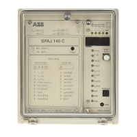
Fig. 3. Terminal arrangement of the overcurrent and earth-fault relay type SPAJ 140 C.
68
69
77
78
80
81
Made in Finland
1
2
3
4
5
6
7
8
9
25
26
27
61
62
63
65
66
74
75
70
71
72
10
11
Serial Port
SPA

 Loading...