7
be configured to obtain the required protection
functions.
SGR3 / 6
SGR1 / 8
IL1
IL2
IL3
SGR3 / 1
SGR1 / 1
SGR3 / 2
SGR2 / 1
SGR2 / 2
SGR1 / 2
SGR3 / 3
SGR1 / 3
SGR3 / 4
SGR2 / 3
SGR2 / 4
SGR1 / 4
SGR3 / 5
SGR1 / 5
SGR2 / 5
SGR2 / 6
SGR1 / 6
SGR3 / 7
SGR1 / 7
SGR3 / 8
SGR2 / 7
SGR2 / 8
I>
I>>
t>>
t>, k
to>, ko
Io>
to>>
Io>>
Io
BS
SGB / 1
SGB / 2
SGB / 3
SGB / 4
SGB / 5
SGB / 8
REMOTE SETTINGS
RELAY RESET
1
SGB / 6
RESET+
PROGRAM
1
SGB / 7
RESET+
PROGRAM
1
1
1
SGF1 / 4
SS1
SS2
SPCJ 4D29
TS1
TS2
SS3
RESET
TRIP
0.1...1s
A
B
C
D
F
IRF
E
START 1
START 2
SIGNAL 1
SIGNAL 2
TRIP
IRF
(AR2)
(AR1)
(AR3)
SGF2 / 8
SGF2 / 7
SPTU ___R1
REDUCED BLOCK DIAGRAM
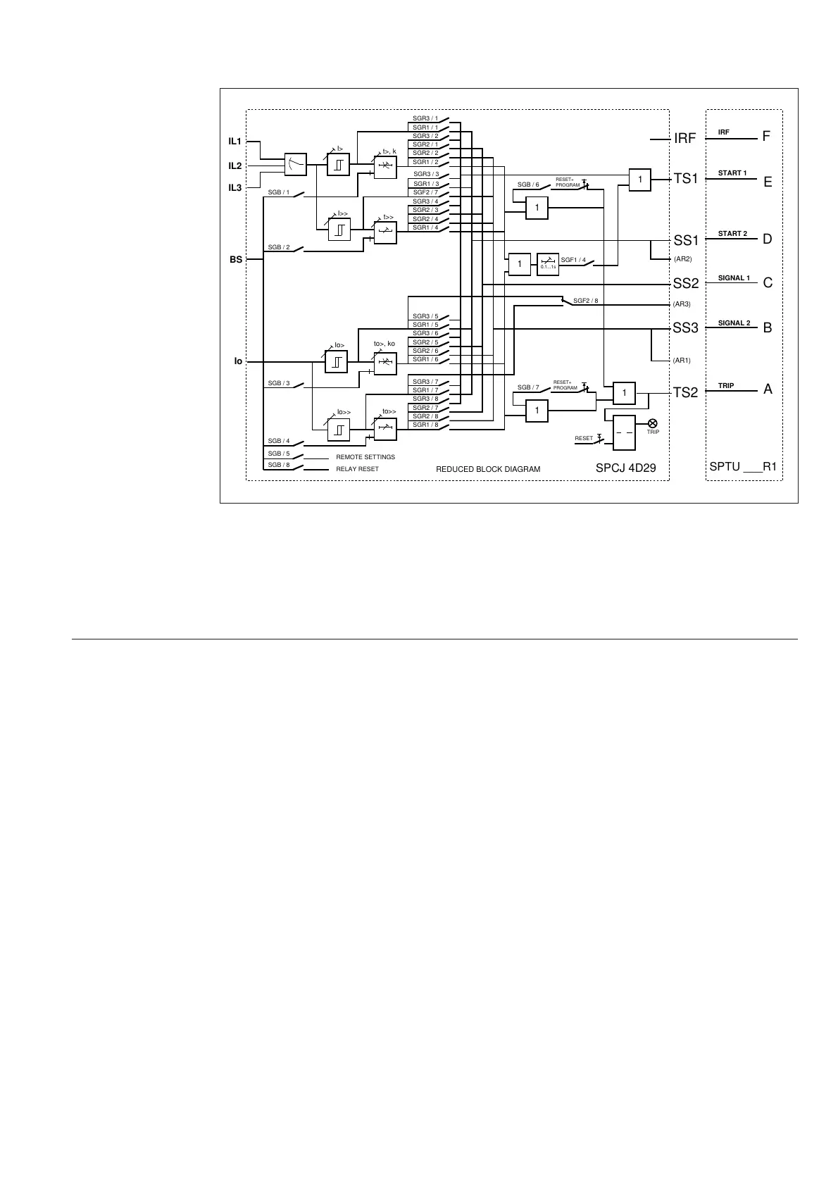
Fig. 4. Signal diagram of the combined overcurrent and earth-fault relay type SPAJ 140 C
The functions of the blocking and start signals
are selected with the switches of switchgroups
SGF, SGB and SGR. The checksums of the
switchgroups, are found in the setting menu of
the protection relay module. The functions of
the different switches are explained in detail in
the user´s manual of the protection relay mod-
ule SPCJ 4D29.
Signal diagram
The figure below schematically illustrates how
the start, trip, control and blocking signals can
I
L1
, I
L2
, I
L3
Energizing current of phase L1, L2 and L3
I
0
Neutral current (Residual current)
BS Blocking or control signal
SS1 Start signal 1
SS2 Start signal 2
SS3 Start signal 3
TS1 Operate signal 1 (Trip signal 1)
TS2 Operate signal 2 (Trip signal 2)
BS Blocking signal
AR1...3 Auto-reclose start signals (not in use in relay SPAJ 140 C)
IRF Internal relay failure
SGF Switchgroup for functions
SGB Switchgroup for blockings
SGR Switchgroup for relay configuration
Signal
abbreviations