8
Operation
indicators
A) The indicator TRIP is lit when one of the
protection stages operates. When the protec-
tion stage resets, the red indicator remains lit.
B) If the display is dark when one of the protec-
tion stages I>, I>>, I
0
> or I
0
>> operates, the
faulty phase or the neutral circuit is indicated
with a yellow LED. If, for instance, the TRIP
indicator glows red, and the indicators I
L1
and I
L2
at the same time are lit, overcurrent
has occurred on phase L1 and L2.
C) Besides being a code number at data presen-
tation, the leftmost red digit in the display
serves as a visual operation indicator. An
operation indicator is recognized by the fact
that the red digit alone is switched on. The
following table named OPERATION IND.
on the relay front panel is a key to the
function code numbers used.
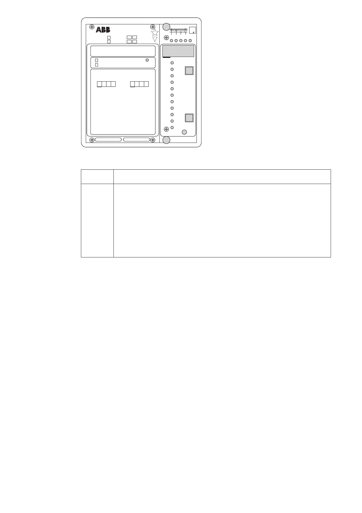
Ser.No.
n
=
n
=
SPAJ 140 C
aux
SPCJ 4D29
REGISTERS
OPER.IND.
0000
0
1
2
3
4
5
6
7
8
n
/
L3
n
/
L1
n
/
L2
max
(15min)
on
/
1
2
3
4
5
6
7
8
>
START
>
TRIP
>
>
TRIP
>
>
START
>
o
START
>
>
o
START
>
o
TRIP
>
>
o
TRIP
9
%
)(
>
%
)(
>>
()
>
o
%
(
o
)
%
>>
CBFP
9
t
t
t
t
[]
[]
[]
[]
I
0074A
I
(
)
I
(
)
o
I
I
I
I
I
I
I
I
I
I
I
I
I
I
I
I
I
I
I
I
I
n
I
/
I
80...265V
~
–
18...80V
–
5A1A
1A 5A
2
5
U
f
n
= 50Hz
60Hz
RS 611 006 -
[
SGR
SGB
SGF
SPCJ 4D29
TRIP
PROGRAM
RESET
STEP
L1 L2 L3
0
IRF
3
>
I
I
I
II
I
>
n
I
I
/
k
s
>
t
]
n
>
>
I
I
/
s
>
>
[]
t
s
>
k
[]
t
n
0
>
I
I
/
s
>
>
o
t
[]
n
>
>
o
I
/
I
0012A
0
0
Indication Explanation
1 I> START = The low-set stage I> of the overcurrent unit has started
2 I> TRIP = The low-set stage I> of the overcurrent unit has operated
3 I>> START = The high-set stage I>> of the overcurrent unit has started
4 I>> TRIP = The high-set stage I>> of the overcurrent unit has operated
5I
0
> START = The low-set stage I
0
> of the earth-fault unit has started
6I
0
> TRIP = The low-set stage I
0
> of the earth-fault unit has operated
7I
0
>> START = The high-set stage I
0
>> of the earth-fault unit has started
8I
0
>> TRIP = The high-set stage I
0
>> of the earth-fault unit has operated
9 CBFP = Circuit breaker failure protection has operated
D) The TRIP indications persist when the pro-
tection stage returns to normal. The indica-
tor is reset by pushing the RESET/STEP
push-button.
Further, the indicators may be reset via the
external control input 10-11 by applying a
control voltage to the input, provided switch
SGB/8 is in position 1.
The basic protection relay functions are not
depending on the state of the operation indica-
tors, reset or non-reset. The relay is permanently
operative.
If a protection stage starts, but not operates,
because the energizing quantity goes below the
set start current before the operate time circuit
has timed out, the start indicators are normally
automatically switched off. However, by means
of the switches SGF2/1…4 the start indications
may be made persistant which means that they
are to be manually reset by pushing the RESET/
STEP push-button. The persistent indications
are obtained through the following switch set-
tings.
SGF2/1 = 1 manual reset of I> start indication
SGF2/2 = 1 manual reset of I>> start indication
SGF2/3 = 1 manual reset of I
0
> start indication
SGF2/4 = 1 manual reset of I
0
>> start indication
On delivery of the relay from the factory the
switches SGF2/1…4 are preset at 0.
E) Shortly after the internal self-supervision
system has detected a permanent relay fault
the red IRF indicator is switched on and the
output relay of the self-supervision system
operates. Further, in most fault situations an
autodiagnostic fault code is shown in the
display. The fault code is composed of a red
figure 1 and a green code number which
indicates fault type. The fault code persists
until the STEP/RESET push-button is
pressed. When a fault code appears on the
display, the code number should be recorded
for statistical and maintenance purposes.