11
Intermodular
control signals
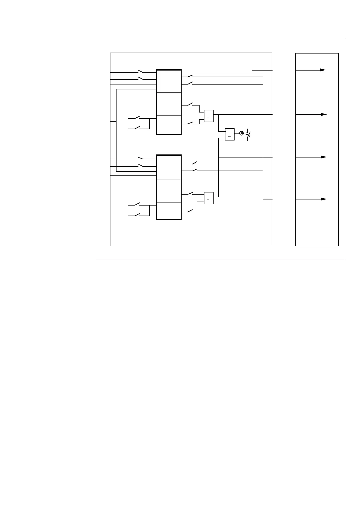
The figure below illustrates the configuration
of the blocking and control signals (SGB) and
alarm signals (SGR), and the selection of the
check functions (SGF) of the stages.
>
1
CB13
CB23
ALARM
U1
U3
U
BS23
CS23
CS13
BS13
SGR/5
SGR/7
SGR/1
SGR/3
CSF13
NC13
SGB/3
SGB/1
NC23
CSF23
SGB/4
SGB/2
IR
D
C
A
B
SPCU 3D45 SPTU __ R
SC13
VC13
SC23
VC23
>
1
>1
SGF/3
SGF/4
SGF/7
SGF/8
II
I
CS23
BS23
U3
U2
CS13
BS13
U1
U3
SGF/1
SGF/2
SGF/5
SGF/6
Fig. 6. Control signals between the modules of the synchro-check relay SPAU 140 C and the
configuration switches.
U1,U2,U3 Measured voltages
CB13 Close permission/close command, stage 1
CB23 Close permission/close command, stage 2
ALARM Alarm signal from stages 1 and 2
BS13 External blocking signal to stage 1
BS23 External blocking signal to stage 2
CS13 External control signal to stage 1, request for CB closing
CS23 External command signal to stage 2, request for CB closing
IRF Signal for internal relay fault
SGF Switchgroup for configuring the functions of the synchro-check relay
SGB Switchgroup for configuring the blocking and command functions
SGR Switchgroup for configuring the alarm functions


 To Next Page