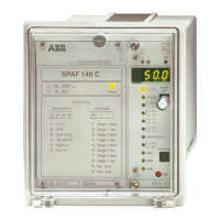
The document describes the SPAF 140 C Frequency Relay and the SPCF 1D15 Combined Frequency and Rate of Change of Frequency Relay Module, both manufactured by ABB. These devices are designed for frequency protection in power systems.
Function Description
The SPAF 140 C is a secondary relay connected to the voltage transformer of the network to be protected. It incorporates one relay module, the combined frequency and rate of change of frequency module type SPCF 1D15. This module provides four protection stages, each with its own frequency function (f), its own rate of change of frequency function (df/dt), and two adjustable operate times (t and t').
The relay is designed for overfrequency/underfrequency protection of generators, motors, and other equipment. It can also be used for monitoring the power balance in the network and disconnecting parts of the network in situations of power deficiency. When the frequency limit of a stage is set below the rated frequency, the protection stage operates as an underfrequency stage. Conversely, if the frequency limit is set above the rated frequency, it operates as an overfrequency stage. The frequency setting can be the rated frequency.
The df/dt function of a protection stage is based on the principle that the frequency function, which means that a protection stage operates as an underfrequency stage, the sign of the df/dt function is negative. If the df/dt function is positive, the absolute value of the rate of change of frequency exceeds the df/dt limit. When required, the frequency function and the df/dt function can be combined so that the criteria for operation of both functions have to be fulfilled at the same time.
A preset condition can be fulfilled, the stage starts, and, at the same time, it activates a tripping circuit. A start signal can be programmed for the output relays. When the stage times out, the relay produces a trip signal. The trip signal can be linked to the desired output relay.
The SPCF 1D15 module measures frequency by determining the time between zero crossings of a signal. The frequency is calculated as a moving average so that the length of the averaging can be selected by the customer. The number of cycles to be used for the calculation can be selected in the range from 3 to 20 cycles. The measurement response time is short and consistent.
The rate of change of frequency measurement is based on two successive frequency values, calculated as moving values over three cycles. The number of cycles to be used in the frequency measurement does not affect the measurement of the rate of change of frequency.
The relay module also includes a self-supervision system that continuously monitors the microprocessor, program execution, and electronics. If a permanent fault is detected, the red IRF indicator on the front panel lights up, and a control signal is sent to the self-supervision system's output relay.
Important Technical Specifications
Voltage Input (programmable): 100 V (110 V, 115 V, 120 V)
Terminal numbers: 13-14
Continuous voltage withstand: 2 x Un
Rated burden of voltage input at Un: <0.5 VA
Output Contacts:
- Trip contacts:
- Terminal numbers: 85-86, 87-88
- Rated voltage: 250 V ac/dc
- Continuous current carrying capacity: 5 A
- Make and carry 0.5 s: 30 A
- Make and carry 3 s: 15 A
- Breaking capacity for dc when the control circuit time constant L/R ≤40 ms at the control voltage levels:
- 220 V dc: 1 A
- 110 V dc: 3 A
- 48 V dc: 5 A
- Signal contacts:
- Terminal numbers: 68-69, 70-71-72
- Rated voltage: 250 V ac/dc
- Continuous current carrying capacity: 5 A
- Make and carry 0.5 s: 10 A
- Make and carry 3 s: 8 A
- Breaking capacity for dc when the control circuit time constant L/R ≤40 ms at the control voltage levels:
- 220 V dc: 0.15 A
- 110 V dc: 0.25 A
- 48 V dc: 1 A
External Control Inputs:
- Blocking/control (BS1...BS4): 10-11, 22-23, 45-46, 47-48
- External control voltage: 18...250 V dc or 80...250 V ac
- Current drain of activated control input: 2...20 mA
Power Supply Module:
- SPTU 240R4:
- Rated voltage Un: 100/120/230 V ac
- Operative range U: 80...265 V ac
- SPTU 48R4:
- Rated voltage Un: 24/48/60 V dc
- Operative range U: 18...80 V dc
- Power consumption under quiescent/operation conditions: 7 W/9 W
Data Communication:
- Transmission mode: Fibre-optic serial bus
- Coding: ASCII
- Data transfer rate, selectable: 4800 Bd or 9600 Bd
- Bus connection modules for fibre-optic data transfer:
- For plastic core cables: SPA-ZC 21 BB
- For glass-fibre cables: SPA-ZC 21 MM
- Modules with internal power supply unit:
- For plastic core cables: SPA-ZC 17 BB
- For glass-fibre cables: SPA-ZC 17 MM
Insulation Tests (IEC 60255-5):
- Dielectric test: 2 kV, 50 Hz, 1 min
- Impulse voltage test: 5 kV, 1.2/50 µs, 0.5 J
- Insulation resistance measurement: >100 MΩ, 500 Vdc
Electromagnetic Compatibility Tests (IEC 60255-22-1, IEC 61000-4-2, IEC 61000-4-4):
- High-frequency (1 MHz) burst disturbance test:
- Common mode: 2.5 kV
- Differential mode: 1.0 kV
- Electrostatic discharge test:
- Contact discharge: 6 kV
- Air discharge: 8 kV
- Fast transient disturbance test:
- Auxiliary power supply: 4 kV
- I/O ports: 2 kV
Mechanical Environmental Tests (IEC 60255-21-1, IEC 60255-21-2, IEC 60255-21-3):
- Vibration test: Class 2
- Chock/bump test: Class 2
- Seismic test: Class 2
Environmental Conditions:
- Service temperature range: -10...+55°C
- Transport and storage temperature range: -40...+70°C
- Temperature influence: ±0.05%/frequency measurement in the range -10°C...+55°C
- Relative humidity: <0.2%/°C, voltage measurement
- Degree of protection by enclosure of flush-mounting relay case: 95±3%, +55°C, 6 cycles
- Weight of fully equipped relay: IP54, 3 kg
Frequency Function:
- Rated frequency: 30.00...65.00 Hz
- Measuring range: 20.00...75.00 Hz
- Setting range: 25.00...70.00 Hz
- Number of cycles to be used for frequency measurement: 3...20 cycles
- Operation accuracy: ±10 mHz
- Minimum voltage to be measured: 0.25 x Un
Rate of Change of Frequency Function:
- Setting range: 0.2...10.0 Hz/s
- Operation accuracy: ±50 mHz/s
Timer Function:
- Setting range: 0.1...300.0 s
- Operate time accuracy: ±1% or ±30 ms
Undervoltage Blocking:
- Measuring range: 0...1.40 x Un
- Setting range: 0.30...0.90 x Un
- Operation accuracy (in the range 25...70 Hz): ±3% of setting value
Recovery Function:
- Setting range (max. deviation from rated frequency): 0.1...10.0 Hz
- Operate time: 1 s...120 min 59 s
- Operate time accuracy: ±1% or ±30 ms
Usage Features
The relay module features a front panel with indicators for measured values (voltage U and frequency f), rated frequency setting, undervoltage setting, protection stage settings (1-4), df/dt settings, recovery function settings, and switchgroup checksums (SGF, SGB, SGR). A display shows measured values and settings.
Operation Indicators:
- A red number indicates the operation stage, changing when the stage operates.
- A common TRIP indicator on the lower part of the front panel lights up when a trip occurs.
- The display shows the operation code and parameter V10 for detailed information on the operation.
Setting Mode:
- Settings can be adjusted via push-buttons on the front panel or remotely via the serial bus.
- The "STEP" button is used to navigate through menus and increment values.
- The "PROGRAM" button is used to enter submenus, confirm selections, and move the flashing digit during setting.
- A five-minute timeout function returns the relay to normal status if no button is pressed.
- Non-tripping mode can be activated by pressing "PROGRAM" and powering up the module simultaneously, indicated by "---" on the display.
Measured Data:
- The display shows measured phase-to-phase voltage U12 and frequency.
- Registers record parameters at the moment of a fault or trip, including minimum/maximum df/dt and frequency.
- Register 0 provides status information, external blocking signals, and other signals.
- Register A contains the address code and data transfer rate for serial communication.
Trip Test Function:
- Allows activation of output signals one by one for testing.
- The output relays operate according to the configuration of the output relay matrix switches.
- Self-supervision output (IRF) can also be activated.
Remote Control:
- Parameters can be read and written over the serial bus.
- A password (V160) is required to change settings remotely.
- The password can be opened and closed via the serial bus or by power supply failure.
Maintenance Features
Self-Supervision System:
- Continuously supervises the microprocessor, program execution, and electronics.
- Detects permanent faults, lights the red IRF indicator, and sends a control signal to the self-supervision output relay.
- Fault codes appear on the display (e.g., "1" followed by a three-digit green code) to indicate the nature of the fault. These codes cannot be removed by resetting and should be recorded when service is ordered.
- In fault mode, normal relay menus remain operative, allowing access to settings and measured values, though relay operation is inhibited. Serial communication remains active for remote access to relay information.
Memory Management:
- Settings are recorded in two separate memory banks within non-volatile memory.
- Each bank has a checksum test to verify data integrity.
- If one bank is disturbed, settings are taken from the other bank and transferred to the faulty region.
- If both memory banks are damaged, the relay will be out of operation, and an alarm signal will be given via the serial port and IRF output relay.
Cleaning:
- Dust inside the relay case should be removed with compressed air.
- Signs of corrosion on terminals or inside the relay should be checked.
Regular Testing:
- The relay should be subjected to regular tests in accordance with national regulations and instructions. The manufacturer recommends an interval of five years between tests.
- The test procedure includes checking the primary test circuit, the measurement transformers, and the circuit breakers.
- The relay can be tested as a secondary injection test.
- The relay is recommended to be carried out using the normal setting values of the relay and the energizing inputs used. Additional inputs can be included.