3
Description of
operation
Filtering of
energizing input
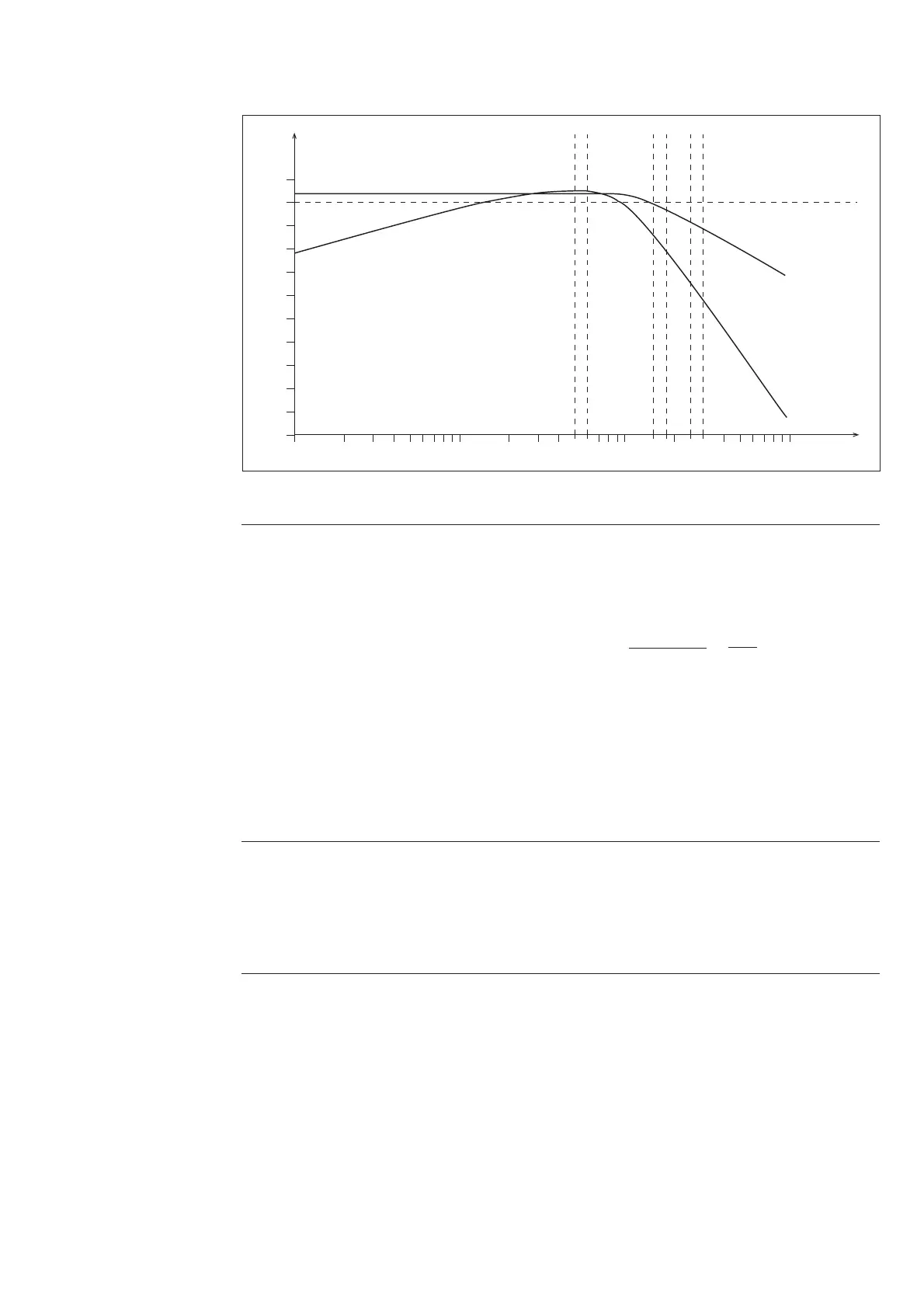
The relay module contains two filters: a lowpass
filter for voltage measurement and a bandpass
filter for frequency measurement. The purpose
of the filters is to suppress the harmonics of the
measured signal. Fig. 1 illustrates harmonics
suppression as a function of frequency.
Fig. 1. Harmonics suppression of the energizing input of relay module SPCF 1D15
Frequency
measurement
Frequency measurement is based on measuring
the time between the zero crossings of a signal.
The frequency is calculated as a moving aver-
age so that the length of the averaging can be
selected by the customer. The number of cycles
to be used for the calculation can be selected in
the range from 3 to 20 cycles.
When the calculation is based on three cycles,
the measurement response time will be short
and, consequently, the trip time as well. On the
other hand, when twenty cycles are used the
response time will be long, but the effect of the
noise possibly occurring in the signal will be
small.
In addition to the filtering described above, the
trip time of the relay is affected by the rated
frequency selected. The minimum trip time of
the relay is obtained from the formula:
t
min
= n + [ms],
where n is the number of cycles used and f
n
the
rated frequency. However, the minimum trip
time is at least 100 ms. Should a trip time shorter
than the calculated time be set for the relay, the
setting will be ignored.
-3f
n
+ 254 85
10 2
Rate of change
of frequency
measurement
The calculation of the rate of change of fre-
quency is based on two successive frequency
values, calculated as moving values over three
cycles. Changing of the number of cycles to be
used in the frequency measurement does not
affect the measurement of the rate of change of
frequency.
When the rate of change of frequency function
is used, the minimum trip time is 150 ms.
Overfrequency When the setting value is above the rated fre-
quency programmed, the protection stage op-
erates as an overfrequency stage. The setting
value cannot be the same as the rated frequency.
Once the frequency exceeds the setting value of
the stage concerned, the stage starts and, at the
same time, a start indicating operation code
appears on the display. Should the stage still be
operated, when the operate time of the stage
expires, it trips, delivering the configured trip
signal.
The tripping of the stages can be prevented by
applying an external control signal BS1...BS5
to the relay module. The switchgroups SGB1...
SGB5 are used for configuring the external
blocking signals. In addition, the undervoltage
blocking function (switchgroup SGR6) can be
used for blocking the stage.
0
A [dB]
f [Hz]
10 100 10001
-100
10
50 60 150 180 250 300
Voltage measurement
Frequency measurement