3
Application
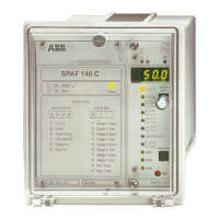
The frequency relay SPAF 140 C is designed to
be used for the overfrequency/underfrequency
protection of generators, motors and other ac
equipment. For instance, even a small devia-
tion from the rated frequency may cause me-
chanical damage to a generator set.
In addition, the frequency relay SPAF 140 C
can be used for monitoring the power balance
in the network and disconnecting parts of the
network in a situation of power deficiency.
The frequency relay SPAF 140 C is a secondary
relay, which is connected to the voltage trans-
formers of the network section to be protected.
The relay incorporates one relay module: the
combined frequency and rate of change of fre-
quency module type SPCF 1D15.
The relay module includes four protection
stages, each of which with its own frequency
function (f), its own rate of change of frequency
function (df/dt) and two adjustable operate
times (t and t’).
When the frequency limit of a stage is set below
the rated frequency, the protection stage oper-
ates as an underfrequency stage. Correspond-
ingly, the stage has the function of an over-
frequency stage, when the frequency level is set
above the rated frequency. The frequency set-
ting cannot be the same as the rated frequency.
The operation of the df/dt function of a pro-
tection stage is based on the same principle as
the frequency function, which means that if a
protection stage operates as an underfrequency
stage, the sign of the df/dt function is negative.
Then the df/dt function starts once the abso-
lute value of the rate of frequency drop exceeds
the df/dt limit. When required, the frequency
function and the df/dt function can be com-
bined so that the criteria for operation of both
functions have to be fulfilled at the same time.
Once a preset condition is fulfilled, the stage
starts and, at the same time, it activates a tim-
ing circuit. No start signal can be programmed
for the output relays. When the stage times out,
the relay produces a trip signal. The trip signal
can be linked to the desired output relay.
Description of
operation