16
Figure 16 - Mounting
Brackets in Position B
Figure 17 – Mounting
Brackets in Position C
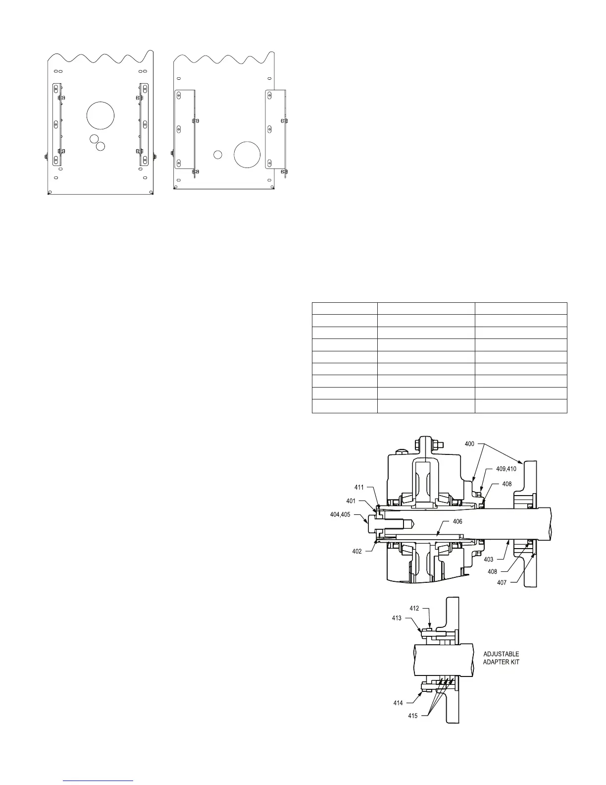
SCREW CONVEYOR ADAPTER ASSEMBLY
1. Install seals (408) into adapter housing as shown in Figure
18. If the optional packing adapter is to be used, install only
one seal in the small end of the adapter. Use extreme care
when installing seals to avoid damage to the seals. Press or
tap seals into place by applying pressure only on the outer
edge of the seal. Make sure seals are install evenly and are
not tilted.
2. If using the optional packing adapter, install the two studs
(413), retaining ring (412), and two nuts (414). Thread the
nuts onto the studs about 4-5 threads. Install the three
braided type seals (415) in a circular direction into the
adapter cavity. Shoulder the braided seals against the
adjustable retaining ring (412). To aid in installation of the
driveshaft in step 7, the braided seals can be attened
out slightly with a soft hammer prior to installation. When
installing the braided seals offset the joints from each other.
3. Lightly tap the large washer (407) into the counterbore on
the large end of the adapter to seal the braided material
installed in Step 2 or the seal installed in Step 1.
4. Place reducer on blocks so that it lays at with the input
shaft down.
5. Position screw conveyor adapter (400) on the reducer
output hub so that the small end (end with four drilled
holes) rests on reducer. The approximate 1/8” piloting
projection should locate in the output seal bore next to the
auxiliary seal. Adapter projection should not touch the face
of the gear case casting.
6. Place four adapter screws (409) and lock washers (410)
through the adapter and thread into the reducer. Tighten
the four cap screws (409) to the torque specied in Table 9.
7. Turn reducer onto its side. Use caution not to damage
either type seals and install drive shaft through the adapter
housing into the reducer. Line up the keyway in the drive
shaft with the keyway in the reducer hub bore. Slide or
gently tap key into reducer through the input shaft side of
the output hub.
8. Install the retaining ring (411) into the screw conveyor
wedge (402). Making sure the drive shaft is fully seated into
the reducer, slide the wedge onto drive shaft.
9. Install keeper plate (401), drive shaft cap screw (404), and
lockwasher (405). Torque to specications in Table 12.
DRIVE SHAFT REMOVAL
To remove the driveshaft from the reducer the following steps
are required.
1. Remove the drive shaft retaining bolt (404) and lock washer
(405), the keeper plate (401), and the retaining ring (411).
2. Referring to Table 10, install the correct size hex head set
screw into the end of the drive shaft until ush. Note TA6307H
and TA7315H does not require a set screw.
3. Position the keeper plate (401) ush against the end of the
drive shaft and with the small end facing out. Next install
the retaining ring (411). When properly installed, the retaining
ring holds the keeper plate (401) in place.
4. Screw removal bolt(s) into the keeper plate (401) and tighten
until the drive shaft wedge (402) is dislodged. Once the drive
shaft wedge (402) is dislodged, pull the assembly free from
the reducer. If installed, remove the hex head set screw from
the end of the drive shaft. The drive shaft can now be easily
removed from the reducer by pulling the drive shaft straight
out of the reducer.
Note: The removal bolt is not the same bolt as the
retaining bolt. Refer to Table 10 for the correct bolt to
be used for removal.
Table 10 – Removal Hardware
Reducer Size Removal Bolt Hex Head Set Screw
TA0107L 3/4-10 x 2 5/8-11 x 3/4
TA1107H 3/4-10 x 2 5/8-11 x 3/4
TA 2115H 3/4-10 x 2 5/8-11 x 3/4
TA3203H 7/8-9 x 2 3/4-10 x 3/4
TA4207H 7/8-9 x 2 3/4-10 x 3/4
TA5215H 7/8-9 x 2 3/4-10 x 3/4
TA6307H 3/8-16 x 2 (4 required) N/A
TA7315H ½-13 x 2 (4 required) N/A
Figure 18 – Screw Conveyor Adapter Assembly
 Loading...


