EasyManua.ls Logo

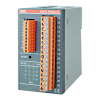
ABB SACE PR021/K

ABB SACE PR021/K
52 pages
To Next Page IconTo Next Page
Loading...
1/52
L3016
1SDH000559R0002
ABB SACE
SACE PR021/K
SACE PR021/K
SIGNALLING UNIT
EN

Questions and Answers:

ABB SACE PR021/K Specifications

General IconGeneral
BrandABB
ModelSACE PR021/K
CategoryIndustrial Electrical
LanguageEnglish

Summary

1. General Information

1.1. Foreword

Introduction and preliminary information about the PR021/K unit and its use.

1.2. Applicable Scenarios

Description of different operational scenarios and unit relationships.

2. Technical Specifications

2.1. Electrical Characteristics

Details of electrical properties, including auxiliary power supply.

2.2. Mechanical Characteristics

Information on casing, protection grade, dimensions, and weight.

2.3. Environmental Conditions

Operating and storage temperature, humidity, and pressure limits.

2.4. Communication Bus

Specifies the type of communication bus used by the unit.

2.5. Internal Relay Characteristics

Parameters for the unit's internal relays.

3. User Interface

3.1. Using the Push-buttons

Instructions for operating the unit's push-button.

3.2. Optical Signals

Explanation of LED indicators and their meanings.

3.3. Terminal Boxes

Description of the terminal connections on the unit.

4. Special Functions

4.1. Reset

Procedure for resetting the PR021/K unit's hardware and software.

4.2. Reset Signals

How to return internal relays to their rest condition.

4.3. Self-Test Function

How to perform a self-test of the unit's relays and indicators.

4.4. Stand-By Function

Enabling a mode where internal relays do not switch.

4.5. Operating Mode

Description of the three operating modes: Normal, Latch, and User.

5. Installation and Setup

5.1. Installation Instructions

Guidelines for mounting and installing the PR021/K unit.

5.2. Connections

Instructions for wiring the unit's terminals.

5.3. Dip-Switch Settings

5.3.1. Example of Dip-Switch Setting

An illustration of dip-switch configuration for the PR021/K unit.

5.3.2. Default Settings

Pre-set dip-switch configurations provided by the manufacturer.

5.3.3. Serial Number

Information on the location of the unit's serial number.

5.4. SACE PR021 K with SACE PR112 Unit (Version with key)

5.4.1. Dip-Switch Settings

Dip-switch settings for PR021/K with PR112 unit (with key).

5.4.2. Signals

Description of signals for PR021/K with PR112 unit in Normal and Latch modes.

5.5. SACE PR021 K with SACE PR112 Unit (Version without key)

5.5.1. Dip-Switch Settings

Dip-switch settings for PR021/K with PR112 unit (without key).

5.5.2. Signals

Description of signals for PR021/K with PR112 unit (without key).

5.6. SACE PR021 K with SACE PR113 Unit

5.6.1. Dip-Switch Settings

Dip-switch settings for PR021/K with PR113 unit.

5.6.2. Signals

Description of signals for PR021/K with PR113 unit (Normal, Latch, User).

5.6.3. Connection of 3 SACE PR021 K units with SACE PR113 P

How to connect multiple PR021/K units to PR113/P.

5.7. SACE PR021 K with SACE PR212 P Unit

5.7.1. Dip-Switch Settings

Dip-switch settings for PR021/K with PR212/P unit.

5.7.2. Signals

Description of signals for PR021/K with PR212/P unit (Normal, Latch).

5.8. SACE PR021 K with SACE PR212 MP-PR222 MP Units

5.8.1. Dip-Switch Settings

Dip-switch settings for PR021/K with PR212MP/PR222MP units.

5.8.2. Signals

Description of signals for PR021/K with PR212MP/PR222MP units (Normal, Latch).

5.9. SACE PR021 K with SACE PR222 DS Unit

5.9.1. Dip-Switch Settings

Dip-switch settings for PR021/K with PR222DS unit.

5.9.2. Signals

Description of signals for PR021/K with PR222DS unit (Normal, Latch).

5.10. SACE PR021 K with SACE PR223 EF Unit

5.10.1. Dip-Switch Settings

Dip-switch settings for PR021/K with PR223EF unit.

5.10.2. Signals

Description of signals for PR021/K with PR223EF unit (Normal, Latch, User).

5.11. SACE PR021 K with SACE PR121 P Unit

5.11.1. Dip-Switch Settings

Dip-switch settings for PR021/K with PR121/P unit.

5.11.2. Signals

Description of signals for PR021/K with PR121/P unit (Normal, Latch, User).

5.12. SACE PR021 K with SACE PR122 P Unit

5.12.1. Dip-Switch Settings

Dip-switch settings for PR021/K with PR122/P unit.

5.12.2. Signals

Description of signals for PR021/K with PR122/P unit (Normal, Latch, User).

5.13. SACE PR021 K with SACE PR123 P Unit

5.13.1. Dip-Switch Settings

Dip-switch settings for PR021/K with PR123/P unit.

5.13.2. Signals

Description of signals for PR021/K with PR123/P unit (Normal, Latch, User).

5.14. SACE PR021 K with SACE PR331 P Unit

5.14.1. Dip-Switch Settings

Dip-switch settings for PR021/K with PR331/P unit.

5.14.2. Signals

Description of signals for PR021/K with PR331/P unit (Normal, Latch, User).

5.15. SACE PR021 K with SACE PR332 P Unit

5.15.1. Dip-Switch Settings

Dip-switch settings for PR021/K with PR332/P unit.

5.15.2. Signals

Description of signals for PR021/K with PR332/P unit (Normal, Latch, User).

5.16. SACE PR021 K with SACE PR333 P Unit

5.16.1. Dip-Switch Settings

Dip-switch settings for PR021/K with PR333/P unit.

5.16.2. Signals

Description of signals for PR021/K with PR333/P unit (Normal, Latch, User).

5.17. Wiring Diagrams

5.17.1. PR112-PR113-PR121-PR122-PR123-PR331-PR332-PR333 + PR021 K

Wiring diagram for PR021/K with various protection units.

5.17.2. PR113 P-PR121 P-PR122 P-PR123 P-PR331 P-PR332 P-PR333 P+3 PR021 K units

Wiring diagram for PR021/K with multiple protection units.

5.17.3. PR212 P or PR212 MP + PR021 K

Wiring diagram for PR021/K with PR212/P or PR212MP units.

5.17.4. PR212 P + PR212 D-L or PR212 D-M + PR021 K

Wiring diagram for PR021/K with PR212/P and PR212/D units.

5.17.5. PR222-PR223-PR222 MP + PR021 K

Wiring diagram for PR021/K with PR222, PR223, PR222MP units.

6. Troubleshooting

6.1. In Case of Fault

Procedure for reporting faults and contacting technical support.

Related product manuals