In the example, the PR021/K has been set as follows:
• Self-test function disabled
• K51 configuration = A-A-A-A
• Master mode
• Baud rate = 19.2Kb/s
• Stand-by function not active
• Manual Reset mode
• Latch mode disabled
• Local bus not terminated
5.4.2. Signals
The signals (K51/1...K51/8) for the SACE PR112 protection release may be divided into 2 modes: Normal and Latch. A
description of the signals in these modes is given below.
5.4.1.1. Normal mode (see par. 4.5.1)
Dip-switch no. 11 to be set to its OFF position.
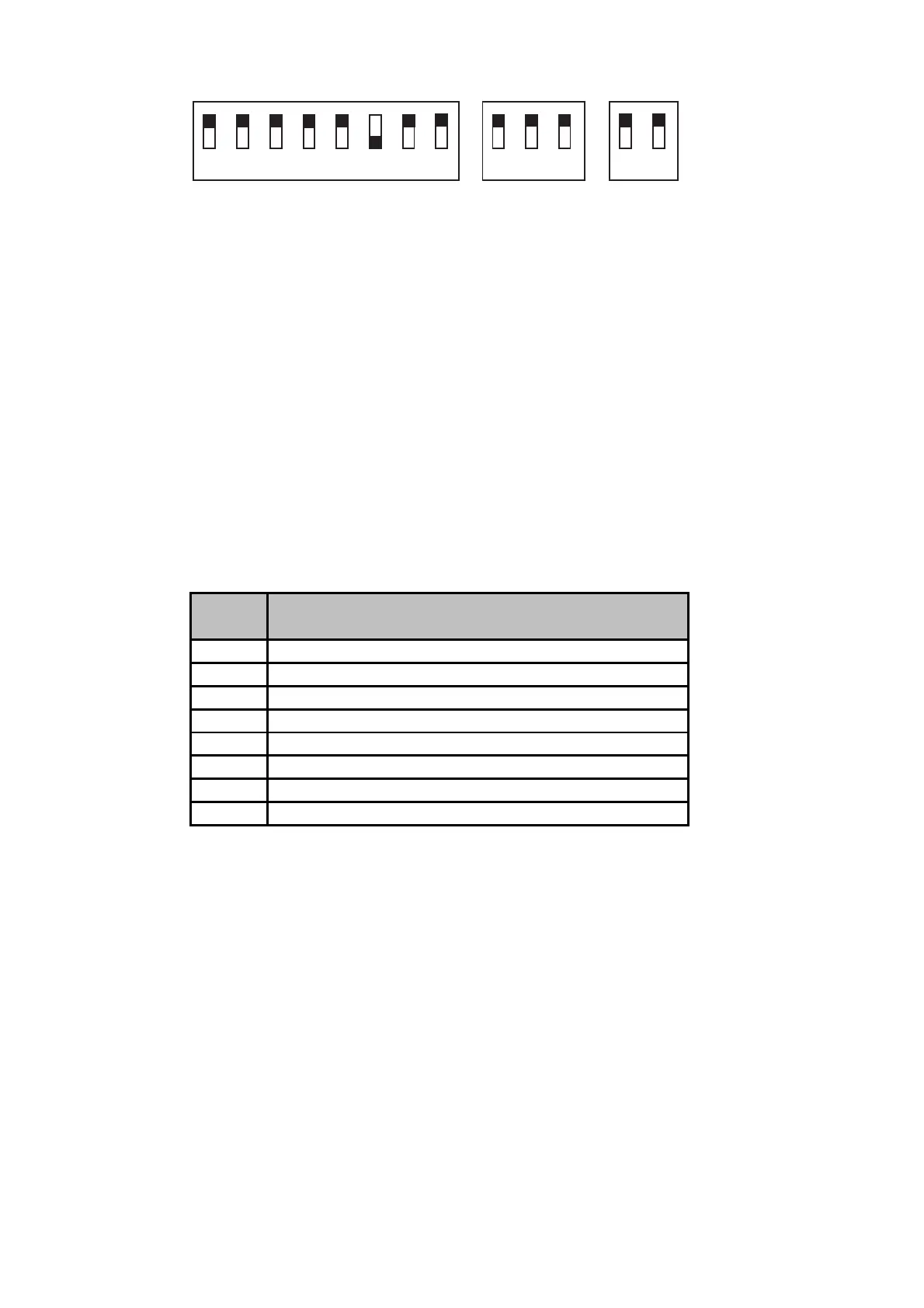
Example of dip-switch settings for the PR021/K unit to be connected to the SACE PR112/P release
12 34
56
78
910
11
12 13
OFF
ON
Note 1: Following a TRIP, the status of the signals is frozen signalling the trip (K51/7) and the protection that caused
it.
Note 2: If dip switch no. 10 (RESET) is set to its “MAN” position, the signals may be reset as described in par. 4.2.
Note 3: If dip switch no. 10 (RESET) is set to its “AUT” position, the signals are reset automatically when the trip on
the protection unit is reset (see par. 4.2).
12345678
91011
12 13
Electric
contact
Event that caused closing of the relay
K51/1
L protection alarm or trip (overload)
K51/2
S protection alarm or trip (selective short-circuit)
K51/3
I protection trip (instantaneous short-circuit)
K51/4
G protection alarm or trip (earth fault)
K51/5
Communication problems on the local bus (bus KO)
K51/6
Internal overtemperature alarm or trip
K51/7
Protection release TRIP alarm
K51/8
L function prealarm (overload)