L3016
1SDH000559R0002
20/52
ABB SACE
SACE PR021/K
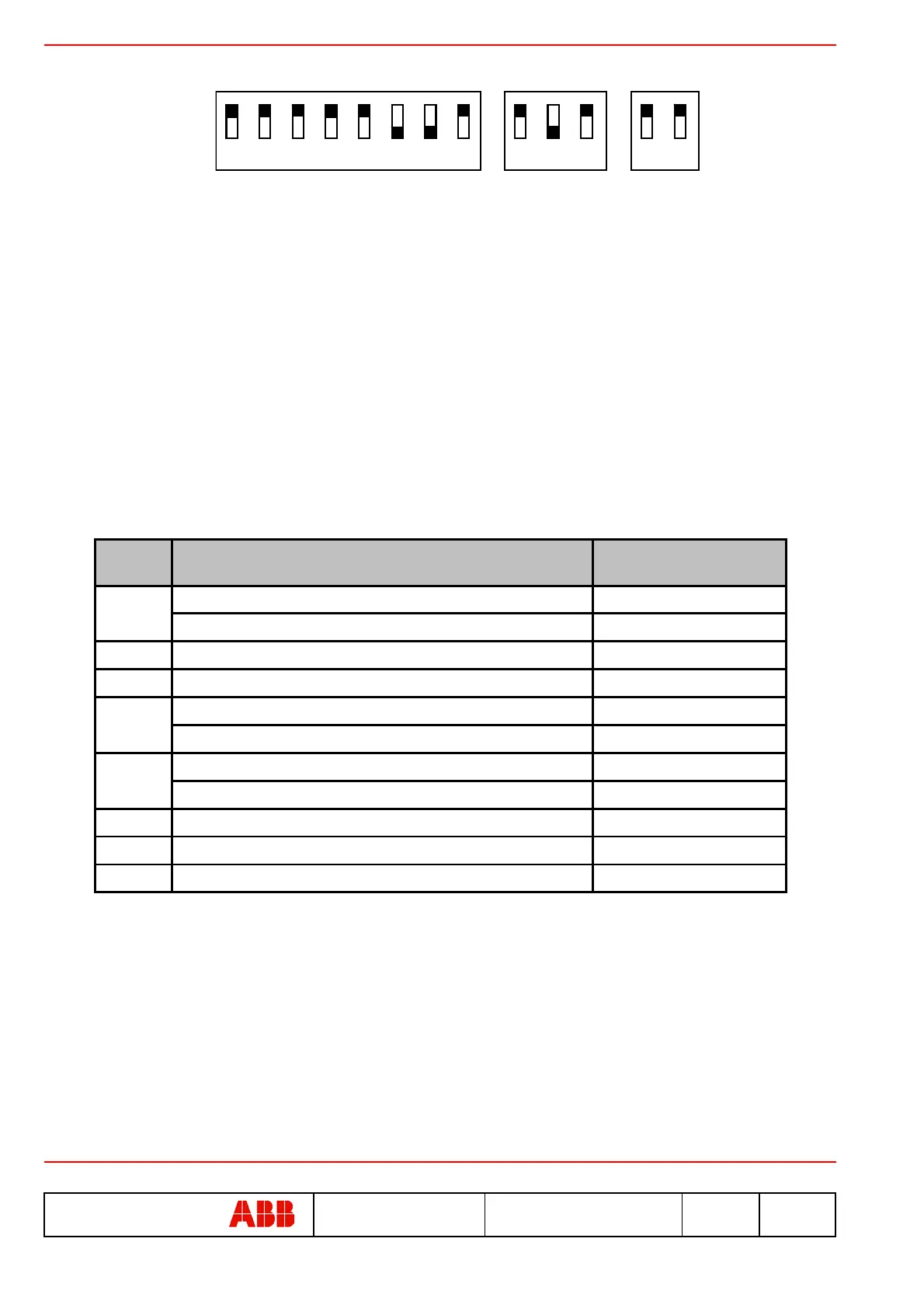
Example of dip-switch settings for the PR021/K unit to be connected to the SACE PR113/P release
In the example, the PR021/K has been set as follows:
• Self-test function disabled
• K51 configuration = A-A-A-A
• Master mode
• Baud rate = 38.4Kb/s
• Stand-by function not active
• Automatic Reset mode
• Latch mode disabled
• Local bus not terminated
OFF
ON
12345678
91011
12 13
5.6.2. Signals
The signals (K51/1...K51/8) for the SACE PR113 protection release may be divided into 3 modes: Normal, Latch and
User. A description of the signals in these modes is given below.
5.6.2.1. Normal mode (see par. 4.5.1)
The dip-switches are to be set as follows: Dip-switch no. 5 = A, Dip-switch no. 11 = OFF.
Note 1: Following a TRIP, the status of the signals is frozen signalling the trip (K51/7) and the protection that caused
it.
Note 2: The signals bearing this marking are not frozen as indicated in Note 1, but follow the status indicated by the
protection irrespective of the protection trip.
Note 3: If dip switch no. 10 (RESET) is set to its “MAN” position, the signals may be reset as described in par. 4.2.
Note 4: If dip switch no. 10 (RESET) is set to its “AUT” position, the signals are reset automatically when the trip on
the protection unit is reset (see par. 4.2).
Note 5: If a trip is caused by a protection function not included in the set of signals (for example, a trip for “protection
G” has occurred but the K51/4 relay was set for the “minimum voltage (MT) coil energized” signal), only the
K51/7 relay (the protection release TRIP alarm) will be switched.
Electric
contact
Event that caused closing of the relay
Selection of dip-switches
no. 2, 3, 4
A = L protection alarm or trip (overload) dip no. 2 = A
B = L function prealarm (overload) dip no. 2 = B
K51/2
S protection alarm or trip (selective short-circuit) ---
K51/3
I protection trip (instantaneous short-circuit) ---
A = G protection alarm or trip (earth fault) dip no. 3 = A
B = Minimum voltage coil (MT) energized dip no. 3 = B
A = Communication problems on the local bus (bus KO) dip no. 4 = A
B = Overtemperature alarm or trip dip no. 4 = B
K51/6
LC1 load control (Note 2) ---
K51/7
Protection release TRIP alarm ---
K51/8
LC2 load control (Note 2) ---
K51/1
K51/4
K51/5