25/52
L3016
1SDH000559R0002
ABB SACE
SACE PR021/K
5.8.2. Signals
The signals (K51/1...K51/8) for the SACE PR212MP protection release may be divided into 2 modes: Normal and Latch.
A description of the signals in these modes is given below.
5.8.2.1. Normal mode (see par. 4.5.1)
Dip-switch no. 11 to be set to its OFF position.
Note 1: Following a TRIP, the status of the signals is frozen signalling the trip (K51/7) and the protection that caused
it.
Note 2: If dip switch no. 10 (RESET) is set to its “MAN” position, the signals may be reset as described in par. 4.2.
Note 3: If dip switch no. 10 (RESET) is set to its “AUT” position, the signals are reset automatically when the trip on
the protection unit is reset (see par. 4.2).
Note 4: If a trip is caused by a protection function not included in the set of signals (for example, a trip for “protection
U” has occurred but the K51/4 relay was set for the “CW alarm or trip” signal), only the K51/7 relay (the protection
release TRIP alarm) will be switched.
Note 5: Backup protection signalling does not undergo freezing as per Note 1.
5.8.2.2. Latch mode (see par. 4.5.2)
Dip-switch no. 11 to be set to its ON position.
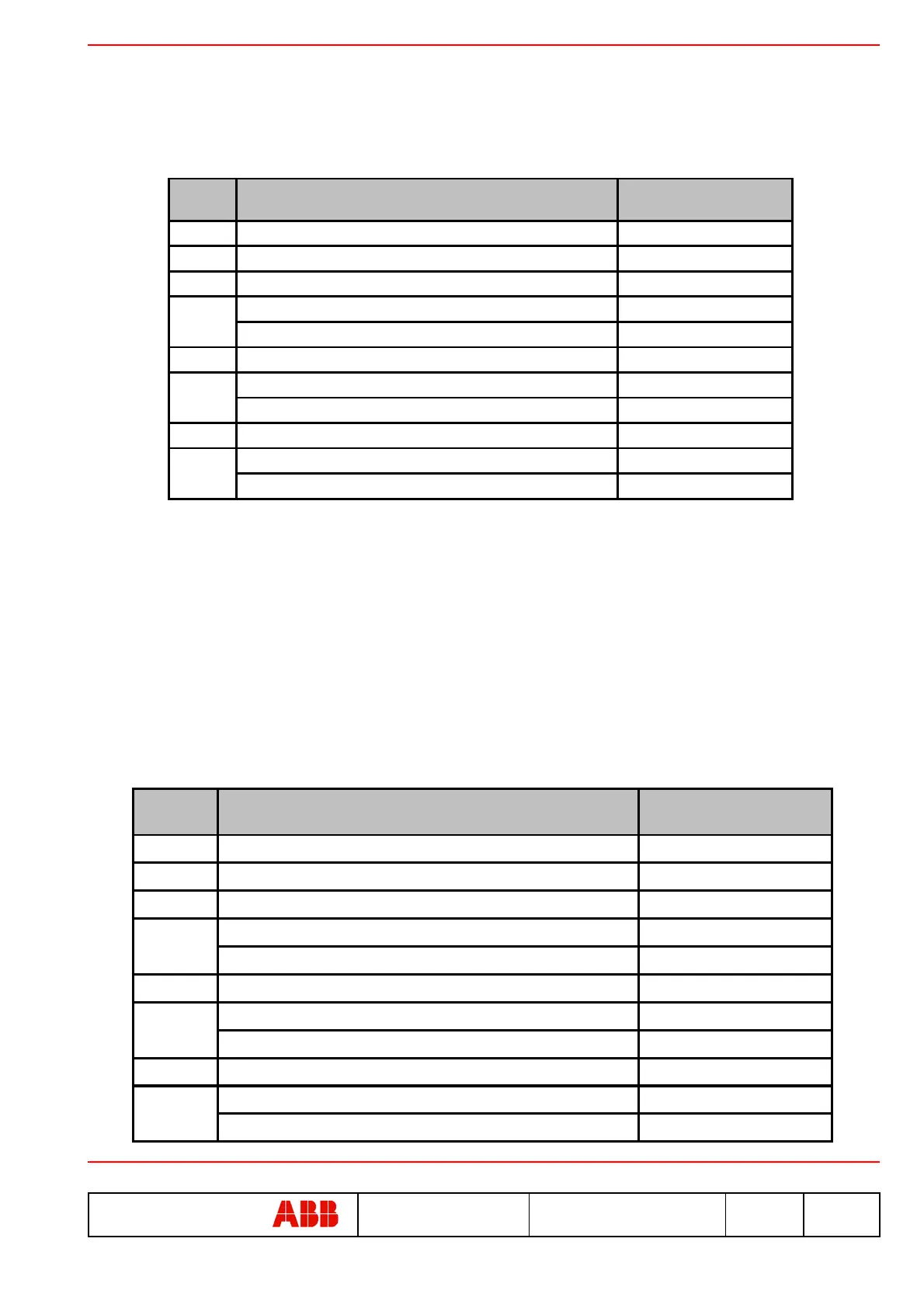
Electric
contact
Event that caused closing of the relay
Selection of dip-switches
no. 2, 3, 4
K51/1
L protection alarm or trip (overload) ---
K51/2
R protection alarm or trip (locked rotor) ---
K51/3
I protection trip (instantaneous short-circuit) ---
A = U protection alarm or trip (phase loss) dip no. 2 = A
B = CW alarm or trip (contacts worn) dip no. 2 = B
K51/5
Communication problems on the local bus (bus KO) ---
A = PTC alarm or trip (motor overtemperature) dip no. 3 = A
B = G.P. generic input status (activated if G.P. = 1) dip no. 3 = B
K51/7
Protection release TRIP alarm ---
A = L Function prealarm (overload) dip no. 4 = A
B = Backup protection alarm (Note 5) dip no. 4 = B
K51/8
K51/6
K51/4
Electric
contact
Event that caused closing of the relay
Selection of dip-switches
no. 2, 3, 4
K51/1
L protection alarm (overload) ---
K51/2
R protection alarm (locked rotor) ---
K51/3
I protection trip (instantaneous short-circuit) ---
A = U protection alarm (phase loss) dip no. 2 = A
B = CW alarm (contacts worn) dip no. 2 = B
K51/5
Communication problems on the local bus (bus KO) ---
A = PTC alarm or trip (motor overtemperature) dip no. 3 = A
B = G.P. generic input status (activated if G.P. = 1) dip no. 3 = B
K51/7
Protection release TRIP alarm ---
A = L Function prealarm (overload) dip no. 4 = A
B = Backup protection alarm dip no. 4 = B
K51/8
K51/6
K51/4