8
COOLING FAN INSTALLATION
WARNING: To ensure that drive is not unexpectedly
started, turn off and lock out or tag power source before
proceeding. Remove all external loads from drive before
removing or servicing drive or accessories. Failure to
observe these precautions could result in bodily injury.
Unpack all components and inspect for shipping damage. Do
not use any component that has been damaged or modied.
Make sure all components are clean and free of any foreign
material prior to assembly. Cooling fan assembly is designed
to t onto the input shaft before placement of sheaves or belt
guard assembly.
Installation for TA4207CF and TA5215CF:
1. Referring to Figure 10, install tapered bushing (9) into bore
of fan blade assembly (2) and loosely install the three set
screws provided with fan. Snug set screws but do not
tighten at this time.
2. Slide fan assembly onto input shaft and install input shaft
key.
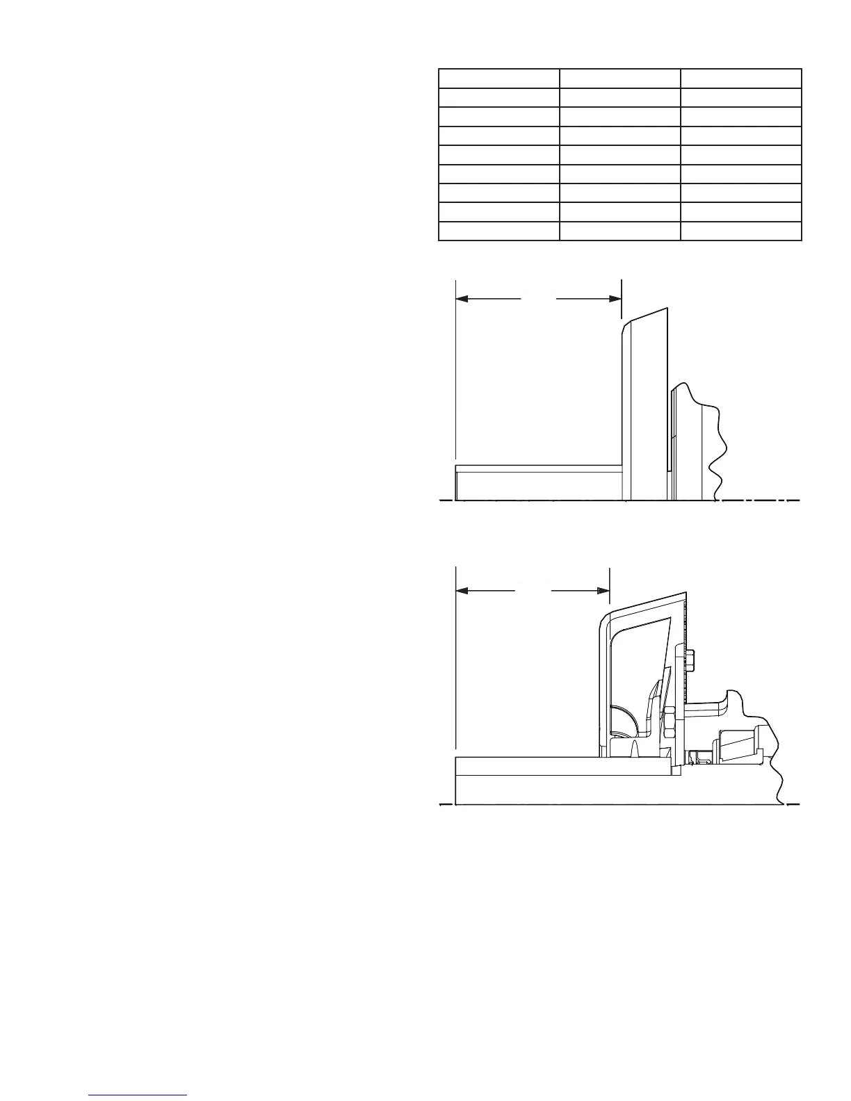
Note: Key is supplied with the TAII reducer. Locate fan
blade edge distance “A” (Figure 10) from end of shaft
per Table 5. Make sure fan assembly rotates without
interference when input shaft is rotated.
3. Alternately tighten the set screws until fan assembly is
securely installed on the input shaft.
4. Recheck fan assembly for proper location and clearance.
Loosen set screws and repeat steps 2 and 3 above if not
properly located.
Installation for TA6307CF through TA12608CF:
1. Referring to Figure 11, install fan guard back plate assembly
(1) using the four bolts (4) provided. Note that the screen
is mounted towards the reducer. Tighten to recommended
torque in Table 8.
CAUTION: Fan guard screen has sharp edges. Use
caution when installing to avoid lacerations.
1. Slide fan blade assembly (2) onto input shaft and install key
and set screws (5).
NOTE: Key is supplied with the TAII reducer.
Position fan blade edge distance “A” (Figure 10) from end of
shaft per Table 6. Make sure fan assembly rotates without
interference when input shaft is rotated. Tighten the two fan
blade set screws (5) securely.
2. Install fan guard cover (3) with four bolts (6), lockwashers (7),
and hex nuts (8). Tighten securely.
3. Verify fan blade rotates freely and does not interfere with fan
guard back plate (1) or fan guard cover (3). Adjust fan blade
if necessary.
Table 6 - Dimensions and Bolt Torque
Reducer Size Dim.”A” inch Torque (Ft.-Lbs.)
TA4207H 3-3/4
TA5215H 4-5/8
TA6307H 4-1/4 33 - 30
TA7315H 4-3/8 33 - 30
TA8407H 5-1/16 33 - 30
TA9415H 6-1/4 33 - 30
TA10507H 6-7/16 33 - 30
TA12608H 6-7/16 33 - 30
A
A
TYPICAL FOR REDUCER SIZES 4 AND 5
TYPICAL FOR REDUCER SIZES 6 - 12
Figure 10 - Fan Blade Placement
 Loading...


